Subaru Legacy III (2000-2003 year). Service manual — part 267
ME(H6DO)-56
MECHANICAL
CYLINDER HEAD ASSEMBLY
E: INSPECTION
1. VALVE SPRING
1) Check valve springs for damage, free length,
and tension. Replace valve spring if it is not to the
specifications presented below.
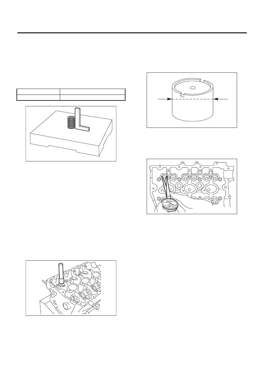
2) To measure the squareness of the valve spring,
stand the spring on a surface plate and measure its
deflection at the top using a try square.
2. INTAKE AND EXHAUST VALVE STEM
SEAL
Replace oil seal with new one, if lip is damaged or
spring out of place, or when the surfaces of intake
valve and valve seat are reconditioned or intake
valve guide is replaced. Use pliers to pinch and re-
move oil seal from valve.
1) Place cylinder head on ST1.
2) Press-fit oil seal to the specified dimension indi-
cated in the figure using ST2.
NOTE:
• Apply engine oil to stem seal before press-fitting.
• When press-fitting stem seal, do not use hammer
or strike in.
ST1
18250AA000 CYLINDER HEAD TABLE
ST2
498857100
VALVE OIL SEAL GUIDE
3. VALVE LIFTER
1) Check valve lifter visually.
2) Measure outer diameter of valve lifter.
Outer diameter:
33.959 — 33.975 mm (1.3370 — 1.3376 in)
3) Measure inner diameter of valve lifter mating
part on cylinder head.
Inner diameter:
34.006 — 34.016 mm (1.3388 — 1.3392 in)
NOTE:
If difference between outer diameter of valve lifter
and inner diameter of valve lifter mating part is over
the limit, replace cylinder head.
Standard:
0.019 — 0.057 mm (0.0007 — 0.0022 in)
Limit:
0.100 mm (0.0039 in)
Free length
46.79 mm (1.8421 in)
Squareness
2.5
°
, 2.0 mm (0.079 in)
ME-00547
ME-00548
ME-00549
ME-00550
ME(H6DO)-57
MECHANICAL
CYLINDER HEAD ASSEMBLY
F: ADJUSTMENT
1. CYLINDER HEAD
1) Make sure that no crack or other damage exists.
In addition to visual inspection, inspect important
areas by means of red lead check.
Also make sure that gasket installing surface
shows no trace of gas and water leaks.
2) Place cylinder head on ST.
ST
18250AA000
CYLINDER HEAD TABLE
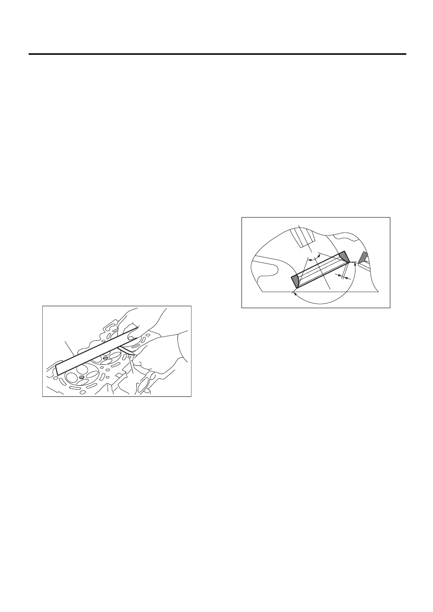
3) Measure the warping of the cylinder head sur-
face that mates with crankcase using a straight
edge and thickness gauge.
If the warping exceeds 0.05 mm (0.0020 in), re-
grind the surface with a surface grinder.
Warping limit:
0.05 mm (0.0020 in)
Grinding limit:
0.1 mm (0.004 in)
Standard height of cylinder head:
124 mm (4.88 in)
NOTE:
Uneven torque for the cylinder head bolts can
cause warping. When reassembling, pay special
attention to the torque so as to tighten evenly.
2. VALVE SEAT
Inspect intake and exhaust valve seats, and correct
the contact surfaces with valve seat cutter if they
are defective or when valve guides are replaced.
Valve seat width: W
Intake
Standard
1.0 mm (0.039 in)
Limit
1.7 mm (0.067 in)
Exhaust
Standard
1.5 mm (0.059 in)
Limit
2.2 mm (0.087 in)
3. VALVE GUIDE
1) Check the clearance between valve guide and
stem. The clearance can be checked by measuring
the outside diameter of valve stem and the inside
diameter of valve guide with outside and inside mi-
crometers respectively.
Clearance between the valve guide and valve
stem:
Standard
Intake
0.030 — 0.057 mm (0.0012 — 0.0022 in)
Exhaust
0.040 — 0.067 mm (0.0016 — 0.0026 in)
Limit
0.15 mm (0.0059 in)
(A) Straight edge
(B) Thickness gauge
ME-00551
( A )
( B )
ME-00552
w
90
˚
150
˚
ME(H6DO)-58
MECHANICAL
CYLINDER HEAD ASSEMBLY
2) If the clearance between valve guide and stem
exceeds the limit, replace valve guide or valve itself
whichever shows greater amount of wear. See fol-
lowing procedure for valve guide replacement.
Valve guide inner diameter:
5.500 — 5.512 mm (0.2165 — 0.2170 in)
Valve stem outer diameter:
Intake
5.455 — 5.470 mm (0.2148 — 0.2154 in)
Exhaust
5.455 — 5.460 mm (0.2148 — 0.2150 in)
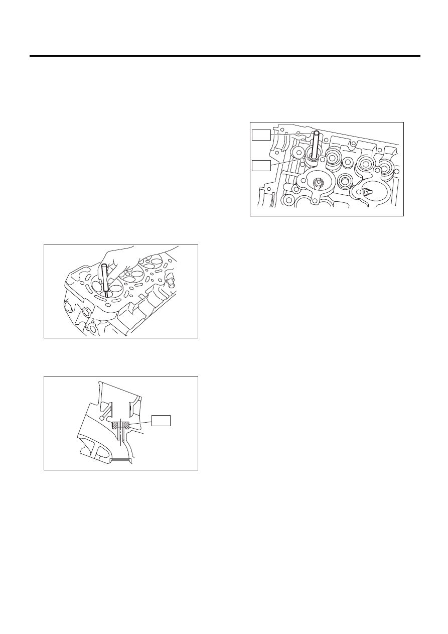
(1) Place cylinder head on ST1 with the com-
bustion chamber upward so that valve guides
enter the holes in ST1.
(2) Insert ST2 into valve guide and press it
down to remove valve guide.
ST1
18250AA000 CYLINDER HEAD TABLE
ST2
499765700
VALVE GUIDE REMOVER
(3) Turn cylinder head upside down and place
ST as shown in the figure.
ST
18251AA000
VALVE GUIDE ADJUSTER
(4) Before installing new valve guide, make
sure that neither scratches nor damages exist
on the inside surface of the valve guide holes in
cylinder head.
(5) Put new valve guide in cylinder, and insert
ST1 into valve guide. Press in until the valve
guide upper end is flush with the upper surface
of ST2.
ST1
499765700
VALVE GUIDE REMOVER
ST2
18251AA000 VALVE GUIDE ADJUSTER
(6) Check the valve guide protrusion.
Valve guide protrusion: L
12.3 — 12.7 mm (0.484 — 0.500 in)
(7) Ream the inside of valve guide with ST.
Gently rotate the reamer clockwise while press-
ing it lightly into valve guide, and return it also ro-
tating clockwise. After reaming, clean valve
guide to remove chips.
ST
499765900
VALVE GUIDE REAMER
NOTE:
• Apply engine oil to the reamer when reaming.
• If the inner surface of the valve guide is torn, the
edge of the reamer should be slightly ground with
an oil stone.
• If the inner surface of the valve guide becomes
lustrous and the reamer does not chips, use a new
reamer or remedy the reamer.
(8) Recheck the contact condition between
valve and valve seat after replacing valve guide.
ME-00553
ME-00554
ST
ST1
ST2
ME-00555
ME(H6DO)-59
MECHANICAL
CYLINDER HEAD ASSEMBLY
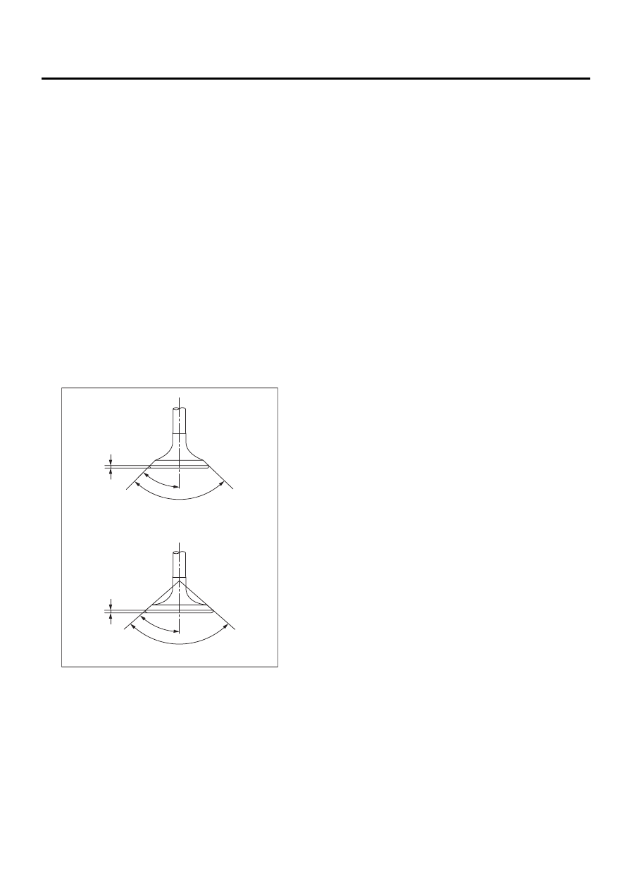
4. INTAKE AND EXHAUST VALVE
1) Inspect the flange and stem of valve, and re-
place if damaged, worn, or deformed, or if “H” is
less than the specified limit.
H:
Intake
Standard
1.0 mm (0.039 in)
Limit
0.8 mm (0.031 in)
Exhaust
Standard
1.2 mm (0.047 in)
Limit
0.8 mm (0.031 in)
Valve overall length:
Intake
103.5 mm (4.075 in)
Exhaust
103.2 mm (4.063 in)
2) Put a small amount of grinding compound on the
seat surface and lap the valve and seat surface. In-
stall a new intake valve oil seal after lapping.
ME-00556
90˚
+1
-0
H
H
45˚
90˚
+1
-0
45˚
Нет комментариевНе стесняйтесь поделиться с нами вашим ценным мнением.
Текст