Subaru Legacy III (2000-2003 year). Service manual — part 265
ME(H6DO)-48
MECHANICAL
REAR CHAIN COVER
15.Rear Chain Cover
A: REMOVAL
1) Remove crankshaft pulley. <Ref. to ME(H6DO)-
38, REMOVAL, Crankshaft Pulley.>
2) Remove front chain cover. <Ref. to ME(H6DO)-
39, REMOVAL, Front Chain Cover.>
3) Remove timing chain. <Ref. to ME(H6DO)-41,
REMOVAL, Timing Chain Assembly.>
4) Remove camshaft sprocket. <Ref. to
ME(H6DO)-46, REMOVAL, Camshaft Sprocket.>
5) Remove crankshaft sprocket.
6) Remove oil pump. <Ref. to LU(H6DO)-11, RE-
MOVAL, Oil Pump.>
7) Remove oil pump relief valve. <Ref. to
LU(H6DO)-13, REMOVAL, Oil Pump Relief
Valve.>
8) Remove water pump. <Ref. to CO(H6DO)-24,
REMOVAL, Water Pump.>
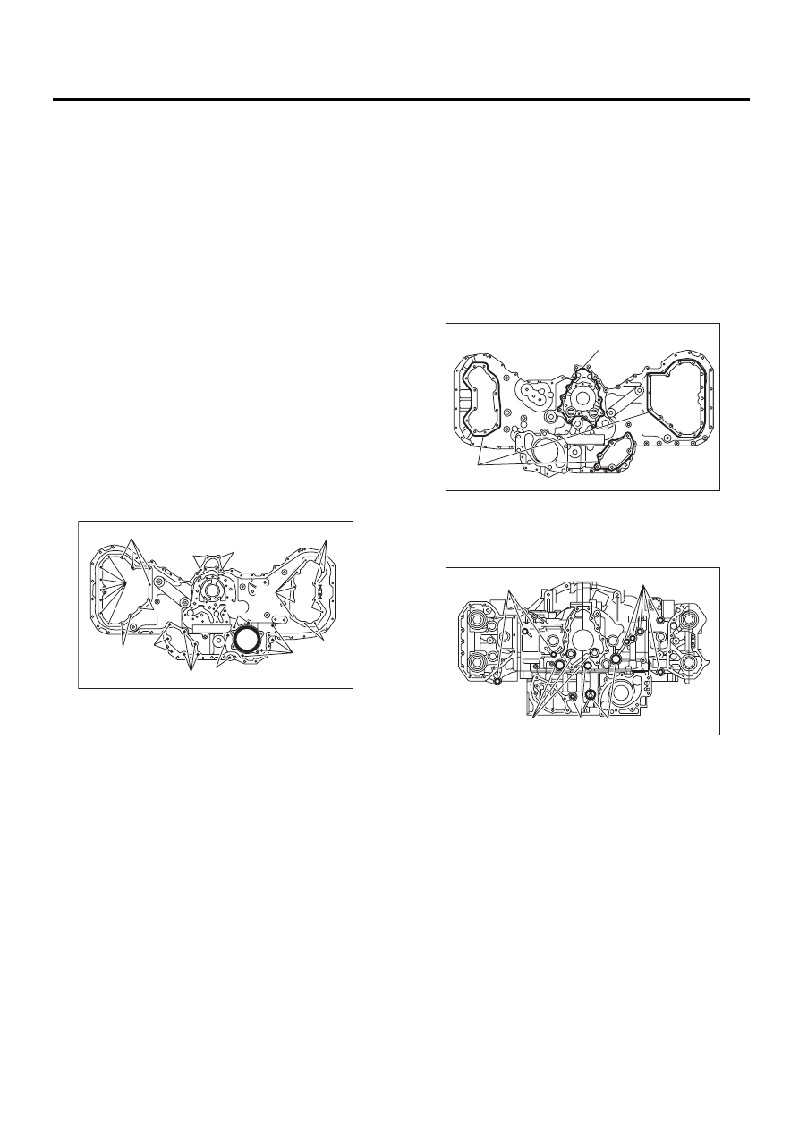
9) Remove rear chain cover.
NOTE:
There are seven different types of mounting bolts.
Sort them into separate containers to avoid confu-
sion at installation.
Bolt dimension:
B: INSTALLATION
1) Remove old fluid gasket on the matching sur-
face, and degrease it.
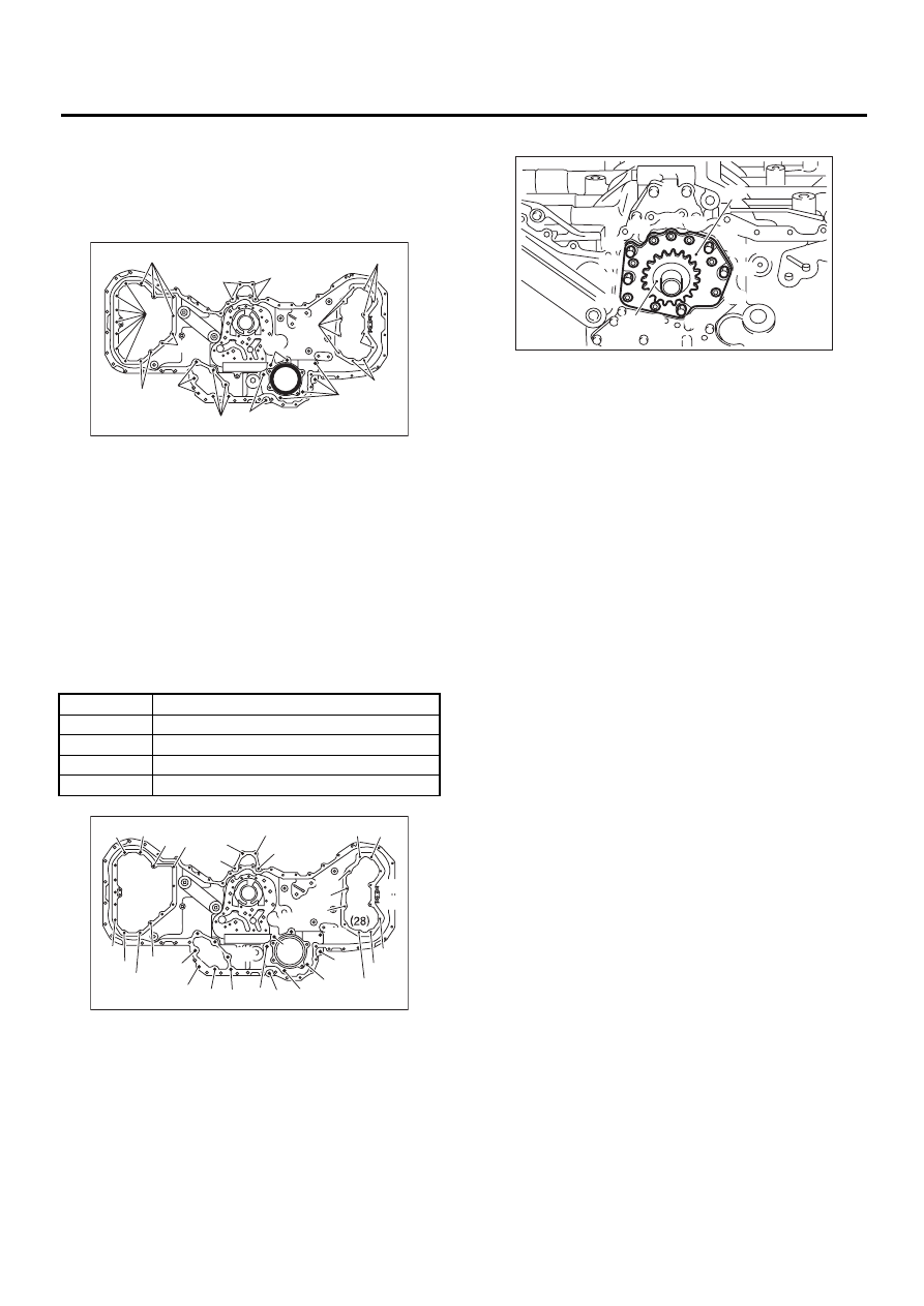
2) Apply fluid gasket to the mating surface of rear
chain cover.
Fluid gasket:
THREE BOND 1280B
Part No.: K0877YA018
Fluid gasket application diameter:
(A) 1.0
±±±±
0.5 mm (0.039
±±±±
0.020 in)
(B) 3.0
±±±±
1.0 mm (0.118
±±±±
0.039 in)
3) Install O-ring.
NOTE:
Do not reuse the O-ring.
(A) 6
×
14
(B) 6
×
18 (Silver)
(C) 6
×
30
(D) 6
×
18
(E) 6
×
40
(F) 6
×
30
(G) 6
×
22
ME-00524
( A )
( B )
( B )
( B )
( C )
( C )
( D )
( D )
( D )
( D )
( E )
( F )
( F )
( G )
( G )
(A) O-ring (Large)
(B) O-ring (Medium)
(C) O-ring (Small)
ME-00525
( A )
( B )
ME-00526
( A )
( A )
( B )
( C )
( C )
ME(H6DO)-49
MECHANICAL
REAR CHAIN COVER
4) Temporarily tighten rear chain cover.
NOTE:
• Do not confuse the mounting positions of the
bolts.
• Replace mounting bolts (G) with new ones.
Bolt dimension:
5) Tighten the bolts in the numerical sequence
shown in figure.
Tightening torque:
6) Install water pump. <Ref. to CO(H6DO)-24, RE-
MOVAL, Water Pump.>
7) Install oil pump relief valve. <Ref. to LU(H6DO)-
13, INSTALLATION, Oil Pump Relief Valve.>
8) Install oil pump. <Ref. to LU(H6DO)-11, IN-
STALLATION, Oil Pump.>
9) Install crankshaft sprocket.
10) Install camshaft sprocket. <Ref. to ME(H6DO)-
46, INSTALLATION, Camshaft Sprocket.>
11) Install timing chain. <Ref. to ME(H6DO)-42, IN-
STALLATION, Timing Chain Assembly.>
12) Install front chain cover. <Ref. to ME(H6DO)-
39, INSTALLATION, Front Chain Cover.>
13) Install crankshaft pulley. <Ref. to ME(H6DO)-
38, INSTALLATION, Crankshaft Pulley.>
(A) 6
×
14
(B) 6
×
18 (Silver)
(C) 6
×
30
(D) 6
×
18
(E) 8
×
40
(F) 8
×
30
(G) 6
×
22
(1) to (11)
9 N·m (0.9 kgf-m, 6.5 ft-lb)
(12) to (19)
20 N·m (2.0 kgf-m, 14 ft-lb)
(20) to (31)
9 N·m (0.9 kgf-m, 6.5 ft-lb)
(32) to (39)
12 N·m (1.2 kgf-m, 8.7 ft-lb)
(40) to (46)
9 N·m (0.9 kgf-m, 6.5 ft-lb)
ME-00524
( A )
( B )
( B )
( B )
( C )
( C )
( D )
( D )
( D )
( D )
( E )
( F )
( F )
( G )
( G )
ME-00527
( 1 )
( 2 )
( 3 )
( 4 )
( 5 )
( 6 )
( 7 )
( 8 )
( 9 )
(10)
(38)
(39)
(40)
(41)
(42)
(43)
(44)
(45)
(35)
(36)
(37)
(34)
(33)
(32)
(46)
(11)
(12)
(13)
(14)
(15)
(16)
(17)
(18)
(19)
(20)
(27)
(26)
(25)
(24)
(23)
(22)
(31)
(30)
(29)
(21)
ME-00528
( 1 )
( 2 )
( 3 )
( 4 )
( 5 )
( 6 )
( 7 )
( 8 )
( 9 )
(10)
(11)
(12)
(13)
( A )
( B )
ME(H6DO)-50
MECHANICAL
CAMSHAFT
16.Camshaft
A: REMOVAL
1) Remove crankshaft pulley. <Ref. to ME(H6DO)-
38, REMOVAL, Crankshaft Pulley.>
2) Remove front chain cover. <Ref. to ME(H6DO)-
39, REMOVAL, Front Chain Cover.>
3) Remove timing chain assembly. <Ref. to
ME(H6DO)-41, REMOVAL, Timing Chain Assem-
bly.>
4) Remove camshaft sprockets. <Ref. to
ME(H6DO)-46, REMOVAL, Camshaft Sprocket.>
5) Remove crankshaft sprocket. <Ref. to
ME(H6DO)-47, REMOVAL, Crankshaft Sprocket.>
6) Remove rear chain cover. <Ref. to ME(H6DO)-
48, REMOVAL, Rear Chain Cover.>
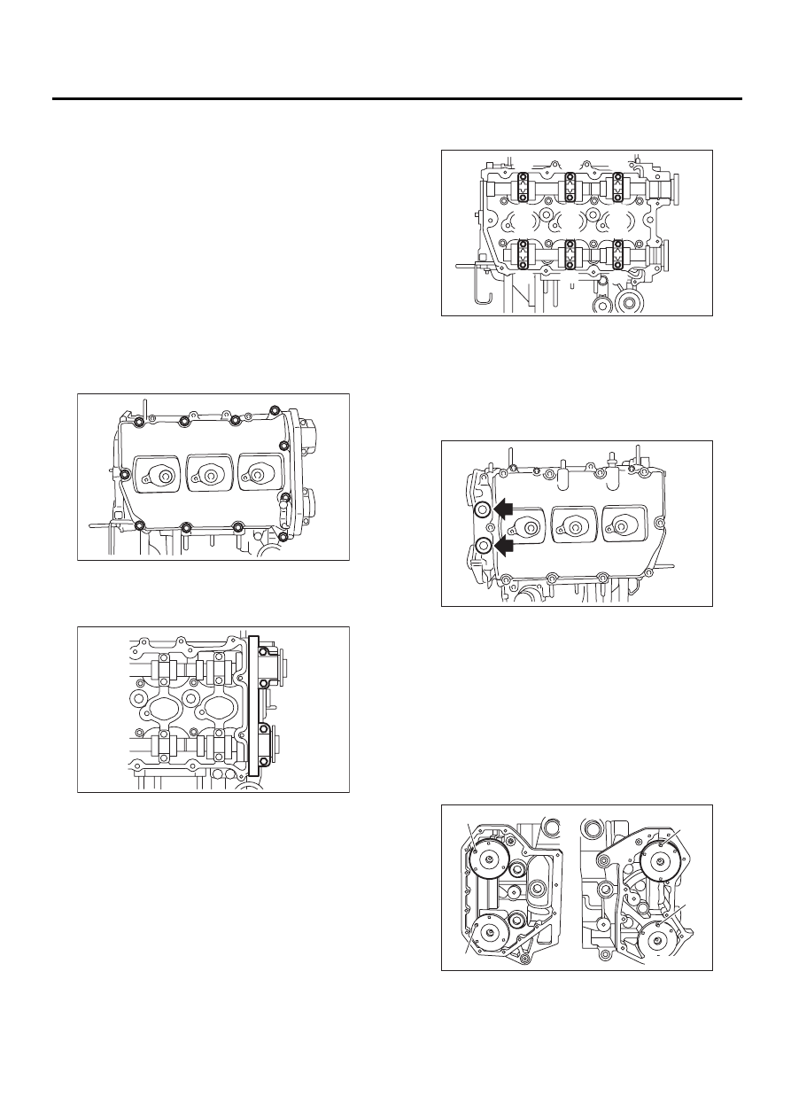
7) Remove rocker cover (RH).
8) Loosen front camshaft cap bolts equally, a little
at a time in numerical sequence shown in the figure
(RH).
9) Remove camshaft cap and intake camshaft
(RH).
10) Loosen camshaft cap bolts equally, a little at a
time in the numerical sequence shown in the figure.
11) Remove camshaft cap and exhaust camshaft
(RH).
CAUTION:
Arrange camshaft caps in order so that they
can be installed in their original position.
12) Remove plug (LH).
13) Similarly, remove left-hand camshafts and re-
lated parts.
B: INSTALLATION
1) Apply a coat of engine oil to camshaft journals
and install camshaft.
NOTE:
When installing camshaft, adjust camshaft front
flange knock pin (A) position as follows:
LH side: 12 o'clock
RH side: 10 o'clock
ME-00529
ME-00530
( 1 )
( 2 )
( 3 )
( 4 )
ME-00531
( 1 )
( 2 )
( 3 )
( 4 )
( 5 )
( 6 )
( 7 )
( 8 )
( 9 )
(10)
(11)
(12)
ME-00532
LH side
RH side
ME-00533
( A )
( A )
( A )
( A )
ME(H6DO)-51
MECHANICAL
CAMSHAFT
2) Install camshaft cap.
(1) Apply fluid packing sparingly to back of front
camshaft cap shown in the figure.
CAUTION:
Do not apply fluid gasket excessively. Failure to
do so may cause excess fluid gasket to come
out and flow toward camshaft journal, resulting
burning stuck of engine.
Fluid gasket:
THREE BOND 1280B
Part No.: K0877YA018
Fluid gasket application diameter:
2.0
±±±±
0.5 mm (0.079
±±±±
0.020 in)
(2) Apply engine oil to cap bearing surface and
install cap on camshaft.
(3) Tighten the camshaft cap bolts in the nu-
merical sequence shown in the figure.
Tightening torque:
16 N·m (1.6 kgf-m, 11.6 ft-lb)
(4) Tighten the front camshaft cap bolts in the
numerical sequence shown in the figure.
Tightening torque:
9.8 N·m (1.0 kgf-m, 7.2 ft-lb)
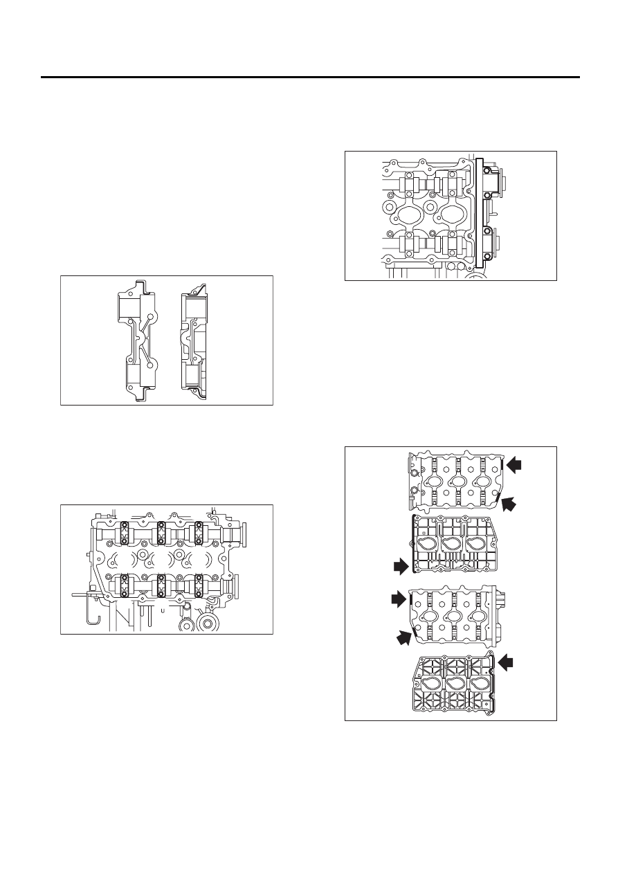
3) Install rocker cover.
(1) Apply fluid gasket sparingly to matching sur-
face of cylinder heads and rocker covers shown
in the figure.
CAUTION:
Do not apply fluid gasket excessively. Doing so
may cause excess fluid gasket to come out and
flow toward camshaft journal, resulting burning
stuck of engine.
Fluid gasket:
THREE BOND 1280B
ME-00534
ME-00535
( 1 )
( 2 )
( 3 )
( 4 )
( 5 )
( 6 )
( 7 )
( 8 )
( 9 )
(10)
(11)
(12)
ME-00536
( 1 )
( 2 )
( 3 )
( 4 )
ME-00537
LH
RH
Нет комментариевНе стесняйтесь поделиться с нами вашим ценным мнением.
Текст