Subaru Legacy III (2000-2003 year). Service manual — part 268

ME(H6DO)-60
MECHANICAL
CYLINDER BLOCK
18.Cylinder Block
A: REMOVAL
1) Remove crankshaft pulley. <Ref. to ME(H6DO)-
38, REMOVAL, Crankshaft Pulley.>
2) Remove front chain cover. <Ref. to ME(H6DO)-
39, REMOVAL, Front Chain Cover.>
3) Remove timing chain assembly. <Ref. to
ME(H6DO)-41, REMOVAL, Timing Chain Assem-
bly.>
4) Remove camshaft sprockets. <Ref. to
ME(H6DO)-46, REMOVAL, Camshaft Sprocket.>
5) Remove crankshaft sprocket. <Ref. to
ME(H6DO)-47, REMOVAL, Crankshaft Sprocket.>
6) Remove rear chain cover. <Ref. to ME(H6DO)-
48, REMOVAL, Rear Chain Cover.>
7) Remove camshafts. <Ref. to ME(H6DO)-50,
REMOVAL, Camshaft.>
8) Remove cylinder head assembly. <Ref. to
ME(H6DO)-54, REMOVAL, Cylinder Head Assem-
bly.>
9) Remove drive plate.
Using ST, lock crankshaft.
ST
498497100
CRANKSHAFT STOPPER
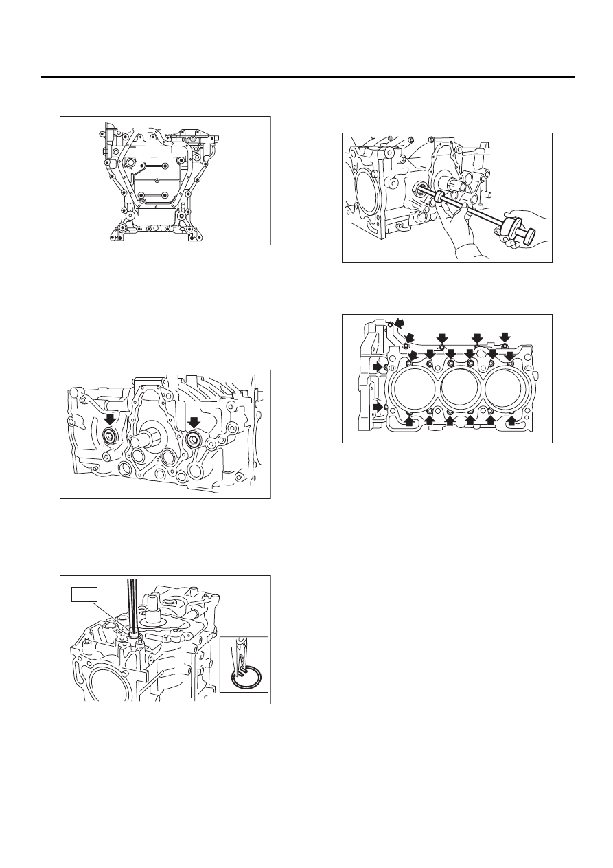
10) Remove crankshaft position sensor plate.
11) Remove crankshaft position sensor bracket.
12) Rotate engine until oil pan comes to the top.
13) Remove bolts which secure lower oil pan to up-
per oil pan.
14) Insert an oil pan cutter blade between cylinder
block-to-oil pan clearance and remove oil pan.
CAUTION:
Do not use a screwdriver or similar tool in place
of oil pan cutter.
15) Remove oil strainer.
ME-00557
ST
ME-00558
ME-00559
ME-00560
ME-00561
ME(H6DO)-61
MECHANICAL
CYLINDER BLOCK
16) Remove bolts which secure upper oil pan to
cylinder block.
Bolt dimension:
17) Remove service hole cover and service hole
plugs using hexagon wrench.
18) Rotate crankshaft to bring #1 and #2 pistons to
bottom dead center position, then remove piston
circlip through service hole of #1 and #2 cylinders
by using ST.
ST
18233AA000
PISTON PIN CIRCLIP PLIER
19) Draw out piston pin from #1 and #2 pistons by
using ST.
ST
499097500
PISTON PIN REMOVER
NOTE:
Be careful not to confuse original combination of
piston, piston pin and cylinder.
20) Similarly remove piston pins from #3, #4, #5
and #6 pistons.
21) Remove bolts which connect cylinder block.
22) Separate left-hand and right-hand cylinder
blocks.
NOTE:
When separating cylinder block, do not allow the
connecting rod to fall and damage the cylinder
block.
23) Remove rear oil seal.
24) Remove crankshaft together with connecting
rod.
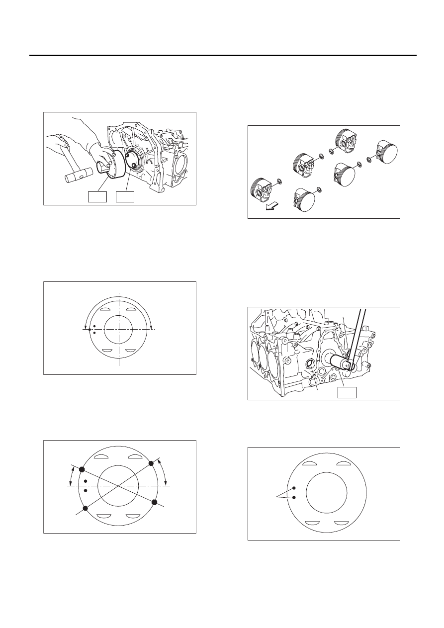
25) Remove crankshaft bearings from cylinder
block using hammer handle.
NOTE:
Do not confuse combination of crankshaft bear-
ings. Press bearing at the end opposite to locking
lip.
26) Draw out each piston from cylinder block using
wooden bar or hammer handle.
NOTE:
Do not confuse combination of piston, piston pin
and cylinder.
(A) 8
×
40
(B) 8
×
65
(C) 8
×
85
(D) 8
×
130
(E) 8
×
24
ME-00562
( A )
( A )
( A )
( A )
( A )
( A )
( A )
( A )
( A )
( A )
( A )
( A )
( A )
( B )
( B )
( B )
( B )
( B )
( B )
( B )
( B )
( B )
( C )
( C )
( D )
( D )
( E )( E )
ME-00563
ME-00564
ST4
ME-00565
ME-00566
ME(H6DO)-62
MECHANICAL
CYLINDER BLOCK
B: INSTALLATION
1) Install ST to cylinder block, then install crank-
shaft bearing.
ST
18232AA000
ENGINE STAND
NOTE:
Remove oil in the mating surface of bearing and
cylinder block before installation. Also apply a coat
of engine oil to crankshaft pins.
2) Position crankshaft and connecting rod on the
#2, #4 and #6 cylinder.
3) Apply fluid gasket to the mating surface of #1, #3
and #5 cylinder block.
Fluid gasket:
THREE BOND 1215B or equivalent
Part No.: 004403007
NOTE:
Do not allow fluid gasket to jut into O-ring grooves,
oil passages, bearing grooves, etc.
Fluid gasket application diameter:
1.0
±±±±
0.2 mm (0.039
±±±±
0.008 in)
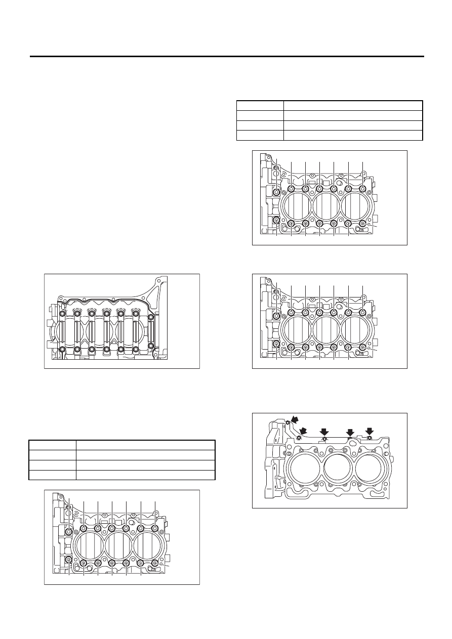
4) Apply engine oil to washers and threads of cylin-
der block connecting bolts. Tighten the bolts follow-
ing the steps below.
(1) Tighten all the bolts in the numerical order
shown in the figure.
Tightening torque:
(2) Tighten all the bolts again in the order
shown in the figure.
Tightening torque:
5) Tighten all the bolts by 90
°
in the order shown in
the figure.
6) Install upper bolts on cylinder block.
Tightening torque:
25 N·m (2.5 kgf-m, 18 ft-lb)
(1) to (11)
25 N·m (2.5 kgf-m, 18 ft-lb)
(12)
20 N·m (2.0 kgf-m, 14 ft-lb)
(13)
25 N·m (2.5 kgf-m, 18 ft-lb)
(14)
20 N·m (2.0 kgf-m, 14 ft-lb)
ME-00567
ME-00568
( 1 )
( 6 )
( 8 )
( 3 ) ( 9 )
( 2 )
( 4 )
( 5 ) ( 7 )
(10)
(11)
(12)
(13)
(14)
(1) to (11)
25 N·m (2.5 kgf-m, 18 ft-lb)
(12)
20 N·m (2.0 kgf-m, 14 ft-lb)
(13)
25 N·m (2.5 kgf-m, 18 ft-lb)
(14)
20 N·m (2.0 kgf-m, 14 ft-lb)
ME-00568
( 1 )
( 6 )
( 8 )
( 3 ) ( 9 )
( 2 )
( 4 )
( 5 ) ( 7 )
(10)
(11)
(12)
(13)
(14)
ME-00568
( 1 )
( 6 )
( 8 )
( 3 ) ( 9 )
( 2 )
( 4 )
( 5 ) ( 7 )
(10)
(11)
(12)
(13)
(14)
ME-00569
ME(H6DO)-63
MECHANICAL
CYLINDER BLOCK
7) Install rear oil seal using ST1 and ST2.
ST1
499597100
CRANKSHAFT OIL SEAL
GUIDE
ST2
499587200
CRANKSHAFT OIL SEAL IN-
STALLER
8) Positioning of piston ring.
(1) Position the top ring gap at (A) in the figure.
(2) Position the second ring gap at (B) in the fig-
ure.
(3) Position the upper rail gap at (C) in the fig-
ure.
(4) Position the expander gap at (D) in the fig-
ure.
(5) Position the lower rail gap at (E) in the fig-
ure.
NOTE:
• Ensure ring gaps do not face the same direction.
• Ensure ring gaps are not within the piston skirt
area.
(6) Install circlip.
Install circlips in piston holes located opposite
service holes in cylinder block, when positioning
all pistons in the corresponding cylinders.
NOTE:
Use new circlips.
9) Installing piston.
NOTE:
Install piston and piston pin to the same cylinder
they were installed before overhaul.
(1) Using ST1, rotate crankshaft until each
small end of connecting rods #3 and #4 is
aligned over service hole (A).
ST1
18252AA000 CRANKSHAFT SOCKET
(2) Apply a coat of engine oil to piston and cyl-
inders.
(3) Install pistons with their front marks (A) fac-
ing the front of engine.
(4) Insert pistons in their cylinders using ST2.
(A) Rear oil seal
(B) Drive plate attaching bolt
ME-00570
ST2
ST1
( A )
( B )
ME-00617
180˚
( A )
( B )
ME-00618
25˚
35˚
( C )
( D )
( E )
ME-00573
Front side
#1
#2
#3
#4
#5
#6
ME-00574
ST1
( A )
( A )
ME-00619
( A )
Нет комментариевНе стесняйтесь поделиться с нами вашим ценным мнением.
Текст