Subaru Legacy III (2000-2003 year). Service manual — part 217

EN(H4SOw/oOBD)-58
ENGINE (DIAGNOSTICS)
LIST OF DIAGNOSTIC TROUBLE CODE (DTC)
*: Immobilizer system equipped model only
35
Purge control solenoid
valve
• The purge control solenoid valve is
not in function.
• The harness connector between
ECM and purge control solenoid valve
is in short or open.
38
Torque control signal (AT) • Abnormal signal is entered from
TCM.
• The harness connector between
ECM and TCM is in short or open.
45
Pressure sensor
• The pressure sensor signal is
abnormal.
• The harness connector between
ECM and pressure sensor is in short
or open.
46
CO resistor (General
spec. vehicles)
• The CO resistor signal is abnormal.
• The harness connector between
ECM and CO resistor is in short or
open.
• The CO valve is not adjusted to
specification.
51
Neutral position switch
(MT)
• The neutral position switch signal is
abnormal.
• The harness connector between
ECM and neutral position switch is in
short or open.
Park/Neutral position
switch (AT)
• The park/neutral position switch
signal is abnormal.
• The shift cable is connected abnor-
mally.
• The harness connector between
ECM and inhibitor switch is in short or
open.
53*
Immobilizer system
Faulty immobilizer system.
<Ref. to IM-2, Basic Diagnostic Procedure.>
85
Charge system
Charge system is abnormal.
Trouble
code
Item
Contents of diagnosis
Index
EN(H4SOw/oOBD)-59
ENGINE (DIAGNOSTICS)
DIAGNOSTIC PROCEDURE WITH DIAGNOSTIC TROUBLE CODE (DTC)
14.Diagnostic Procedure with Diagnostic Trouble Code (DTC)
A: DTC 11 CRANKSHAFT POSITION SENSOR
• DIAGNOSIS:
• No signal entered from crankshaft position sensor when ignition switch is ON.
• The harness connector between ECM and crankshaft position sensor is in short or open.
• TROUBLE SYMPTOM:
• Engine stalls.
• Restarting impossible
CAUTION:
After repair or replacement of faulty parts, conduct CLEAR MEMORY and INSPECTION MODES. <Ref.
to EN(H4SOw/oOBD)-28, OPERATION, Clear Memory Mode.> and <Ref. to EN(H4SOw/oOBD)-26, OP-
ERATION, Inspection Mode.>
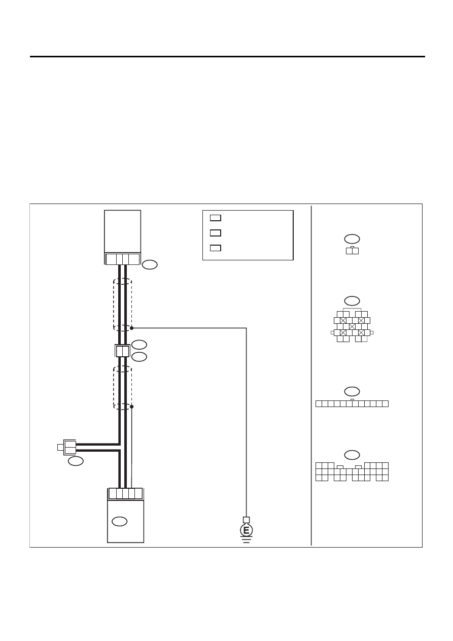
• WIRING DIAGRAM:
EN-01050
1
2
19
17
8
10
B21
B83
E2
E10
5 6 7
8
2
1
9
4
3
10
24
22 23
25
11 12 13 14 15
26
27 28
16 17 18 19
20 21
B135
B21
B83
E10
1 2
B135 ECM
CRANKSHAFT
POSITION
SENSOR
1 2
5
6 7
8
13
14 15
16
9 10
11 12
3 4
17 18
19 20
1 2 3 4 5 6 7 8 9 10 11 12
WITH IMMOBILIZER
WITHOUT IMMOBILIZER
: 2
: 1
1
*
3
*
1
*
2
*
3
*
LHD
RHD
: 7
: 9
2
*
LHD
RHD
: 8
: 7

EN(H4SOw/oOBD)-60
ENGINE (DIAGNOSTICS)
DIAGNOSTIC PROCEDURE WITH DIAGNOSTIC TROUBLE CODE (DTC)
Step
Value
Yes
No
1
CHECK CONDITION OF CRANKSHAFT PO-
SITION SENSOR INSTALLATION.
Are the crankshaft position sensor installing
bolts tightened securely?
Installing bolts are securely
tightened.
Tighten crank-
shaft position sen-
sor installing bolts
securely.
2
CHECK CRANKSHAFT POSITION SENSOR.
1) Remove crankshaft position sensor.
2) Measure resistance between connector ter-
minals of crankshaft position sensor.
Terminals
No. 1 — No. 2:
Is the measured value within the specified
value?
1 — 4 k
Ω
Replace crank-
shaft position sen-
sor.
3
CHECK HARNESS BETWEEN ECM AND
CRANKSHAFT POSITION SENSOR CON-
NECTOR.
1) Connect connector to crankshaft position
sensor.
2) Disconnect connector from ECM.
3) Measure resistance of harness between
crankshaft position sensor connector and
ECM.
Connector & terminal
(B135) No. 8 — (B135) No. 2 (With
immobilizer)
(B135) No. 8 — (B135) No. 1 (Without
immobilizer)
Is the measured value within the specified
value?
1 — 5 k
Ω
Repair harness
and connector.
NOTE:
In this case, repair
the following:
• Open circuit in
harness between
crankshaft posi-
tion sensor and
ECM connector
• Poor contact in
coupling connector
(B21)
4
CHECK HARNESS BETWEEN ECM AND
CRANKSHAFT POSITION SENSOR CON-
NECTOR.
Measure resistance of harness between ECM
connector and chassis ground.
Connector & terminal
(B135) No. 8 — Chassis ground:
Is the measured value less than the specified
value?
10
Ω
Repair ground
short circuit in har-
ness between
crankshaft posi-
tion sensor and
ECM connector.
5
CHECK INPUT SIGNAL FOR ECM.
1) Turn ignition switch to OFF.
2) Set the positive (+) probe and ground lead
of oscilloscope at ECM connector termi-
nals.
3) Measure voltage indicated on oscilloscope
while cranking the engine.
Connector & terminal
(B135) No. 2 (+) — (B135) No. 8 (
−−−−
):
(With immobilizer)
(B135) No. 1 (+) — (B135) No. 8 (
−−−−
):
(Without immobilizer)
Does the measured value exceed the spec-
ified value?
400 mV
Replace crank-
shaft position sen-
sor.
6
CHECK POOR CONTACT.
Check poor contact in ECM connector.
Is there poor contact in ECM connector?
There is poor contact.
Repair poor con-
tact in ECM con-
nector.

EN(H4SOw/oOBD)-61
ENGINE (DIAGNOSTICS)
DIAGNOSTIC PROCEDURE WITH DIAGNOSTIC TROUBLE CODE (DTC)
7
CHECK ECM.
1) Connect all connectors.
2) Erase the memory. <Ref. to EN(H4SOw/
oOBD)-28, OPERATION, Clear Memory
Mode.>
3) Perform inspection mode. <Ref. to
EN(H4SOw/oOBD)-26, OPERATION,
Inspection Mode.>
4) Read out the trouble code. <Ref. to
EN(H4SOw/oOBD)-24, OPERATION,
Read Diagnostic Trouble Code (DTC).>
Is the same trouble code (DTC) as in the
current diagnosis still being output?
DTC is displayed.
Replace genera-
tor.
8
CHECK ANY OTHER TROUBLE CODES AP-
PEARANCE.
Are other trouble codes (DTC) being output?
DTC is displayed.
Proceed with the
diagnosis corre-
sponding to the
trouble code.
A temporary poor
contact.
Step
Value
Yes
No
Нет комментариевНе стесняйтесь поделиться с нами вашим ценным мнением.
Текст