Subaru Legacy III (2000-2003 year). Service manual — part 218
EN(H4SOw/oOBD)-62
ENGINE (DIAGNOSTICS)
DIAGNOSTIC PROCEDURE WITH DIAGNOSTIC TROUBLE CODE (DTC)
B: DTC 12 STARTER SWITCH
• DIAGNOSIS:
• The starter switch signal is abnormal.
• The harness connector between ECM and starter switch is in short or open.
• TROUBLE SYMPTOM:
• Failure of engine to start
CAUTION:
After repair or replacement of faulty parts, conduct CLEAR MEMORY and INSPECTION MODES. <Ref.
to EN(H4SOw/oOBD)-28, OPERATION, Clear Memory Mode.> and <Ref. to EN(H4SOw/oOBD)-26, OP-
ERATION, Inspection Mode.>
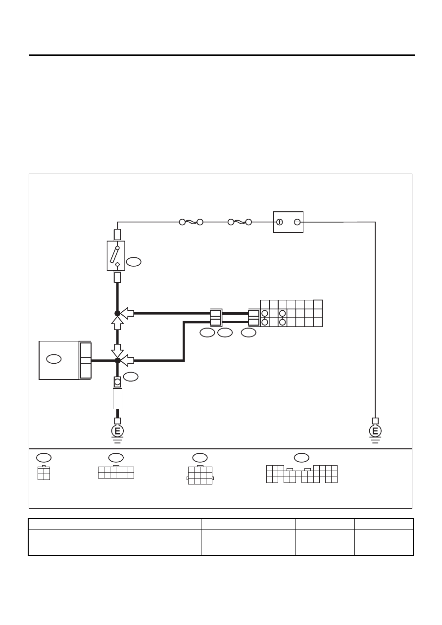
• WIRING DIAGRAM:
Step
Value
Yes
No
1
CHECK OPERATION OF STARTER MOTOR.
Does starter motor operate when ignition
switch starts?
Starter motor operates.
Check starter
motor circuit.
EN-01045
12
INHIBITOR SWITCH
STARTER
MOTOR
7
P
R
N
D
3
2
1
SBF-4
SBF-1
B14
12
11
T7
T3
B12
AT
MT
MT
5 6 7
8
2
1
9
4
3
10
24
22 23
25
11 12 13 14 15
26
27 28
16 17 18 19
20 21
B135
T7
1 2 3 4 5 6
7 8 9 10 11 12
28
B135
ECM
BATTERY
3
1
B72
IGNITION
SWITCH
AT
B72
3 4
1 2
B12
1 2 3 4
5 6 7 8
9 10 11 12

EN(H4SOw/oOBD)-63
ENGINE (DIAGNOSTICS)
DIAGNOSTIC PROCEDURE WITH DIAGNOSTIC TROUBLE CODE (DTC)
2
CHECK HARNESS BETWEEN ECM AND IG-
NITION SWITCH CONNECTOR.
1) Turn ignition switch to OFF.
2) Disconnect connector from ECM.
3) Turn ignition switch to ST.
4) Measure power supply voltage between
ECM connector and chassis ground.
Connector & terminal
(B135) No. 28 (+) — Chassis ground (–):
Does the measured value exceed the spec-
ified value?
10 V
Repair poor con-
tact in ECM con-
nector.
Repair open or
ground short cir-
cuit in harness
between ECM and
ignition switch
connector.
Step
Value
Yes
No
EN(H4SOw/oOBD)-64
ENGINE (DIAGNOSTICS)
DIAGNOSTIC PROCEDURE WITH DIAGNOSTIC TROUBLE CODE (DTC)
C: DTC 13 CAMSHAFT POSITION SENSOR
• DIAGNOSIS:
• No signal entered from camshaft position sensor, but signal entered from crankshaft position sensor.
• The harness connector between ECM and camshaft position sensor is in short or open.
• TROUBLE SYMPTOM:
• Engine stalls.
• Failure of engine to start
CAUTION:
After repair or replacement of faulty parts, conduct CLEAR MEMORY and INSPECTION MODES. <Ref.
to EN(H4SOw/oOBD)-28, OPERATION, Clear Memory Mode.> and <Ref. to EN(H4SOw/oOBD)-26, OP-
ERATION, Inspection Mode.>
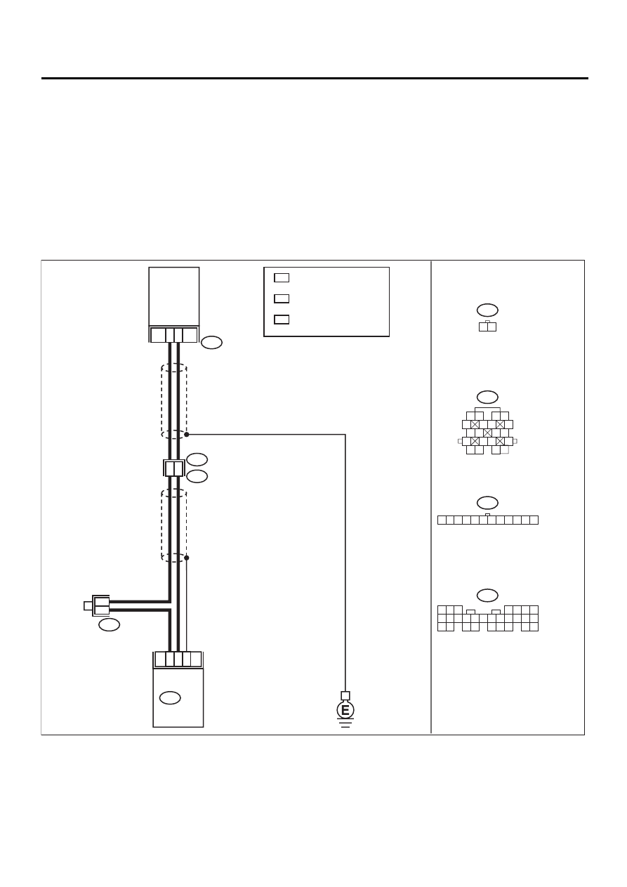
• WIRING DIAGRAM:
EN-01051
5 6 7
8
2
1
9
4
3
10
24
22 23
25
11 12 13 14 15
26
27 28
16 17 18 19
20 21
B135
B21
B83
E15
1 2
1 2
5
6 7
8
13
14 15
16
9 10
11 12
3 4
17 18
19 20
1
2
20
18
8
10
B21
E2
E15
B135 ECM
CAMSHAFT
POSITION
SENSOR
B83
1 2 3 4 5 6 7 8 9 10 11 12
WITH IMMOBILIZER
WITHOUT IMMOBILIZER
LHD
: 1
: 2
3
*
3
*
1
*
2
*
2
*
: 8
RHD : 7
LHD
1
*
: 9
RHD : 8

EN(H4SOw/oOBD)-65
ENGINE (DIAGNOSTICS)
DIAGNOSTIC PROCEDURE WITH DIAGNOSTIC TROUBLE CODE (DTC)
Step
Value
Yes
No
1
CHECK CONDITION OF CAMSHAFT POSI-
TION SENSOR INSTALLATION.
Are the camshaft position sensor installing
bolts tightened securely?
Bolts are securely tightened.
Tighten camshaft
position sensor
installing bolts
securely.
2
CHECK CAMSHAFT POSITION SENSOR.
1) Remove camshaft position sensor.
2) Measure resistance between connector ter-
minals of camshaft position sensor.
Terminals
No. 1 — No. 2:
Is the measured value within the specified
value?
1 — 4 k
Ω
Replace camshaft
position sensor.
3
CHECK HARNESS BETWEEN ECM AND
CAMSHAFT POSITION SENSOR CONNEC-
TOR.
1) Connect connector to camshaft position
sensor.
2) Disconnect connector from ECM.
3) Measure resistance of harness between
camshaft position sensor connector and
ECM.
Connector & terminal
(B135) No. 8 — (B135) No. 1 (With
immobilizer)
(B135) No. 8 — (B135) No. 2 (Without
immobilizer)
Is the measured value within the specified
value?
1 — 5 k
Ω
Repair harness
and connector.
NOTE:
In this case, repair
the following:
• Open circuit in
harness between
camshaft position
sensor and ECM
connector
• Poor contact in
coupling connector
(B21)
4
CHECK HARNESS BETWEEN ECM AND
CAMSHAFT POSITION SENSOR CONNEC-
TOR.
Measure resistance of harness between ECM
connector and chassis ground.
Connector & terminal
(B135) No. 8 — Chassis ground:
Is the measured value less than the specified
value?
5
Ω
Repair ground
short circuit in har-
ness between
camshaft position
sensor and ECM
connector.
5
CHECK INPUT SIGNAL FOR ECM.
1) Turn ignition switch to OFF.
2) Disconnect connector from ECM.
3) Set the positive (+) probe and ground lead
of oscilloscope at ECM connector termi-
nals.
4) Measure voltage indicated on oscilloscope
while cranking the engine.
Connector & terminal
(B135) No. 1 (+) — (B135) No. 8 (
−−−−
):
(With immobilizer)
(B135) No. 2 (+) — (B135) No. 8 (
−−−−
):
(Without immobilizer)
Does the measured value exceed the spec-
ified value?
400 mV
Replace camshaft
position sensor.
6
CHECK POOR CONTACT.
Check poor contact in ECM connector.
Is there poor contact in ECM connector?
There is poor contact.
Repair poor con-
tact in ECM con-
nector.
Нет комментариевНе стесняйтесь поделиться с нами вашим ценным мнением.
Текст