Subaru Legacy III (2000-2003 year). Service manual — part 215
EN(H4SOw/oOBD)-50
ENGINE (DIAGNOSTICS)
DIAGNOSTICS FOR ENGINE STARTING FAILURE
E: FUEL PUMP CIRCUIT
CAUTION:
After repair or replacement of faulty parts, conduct CLEAR MEMORY and INSPECTION MODES. <Ref.
to EN(H4SOw/oOBD)-28, OPERATION, Clear Memory Mode.> and <Ref. to EN(H4SOw/oOBD)-26, OP-
ERATION, Inspection Mode.>
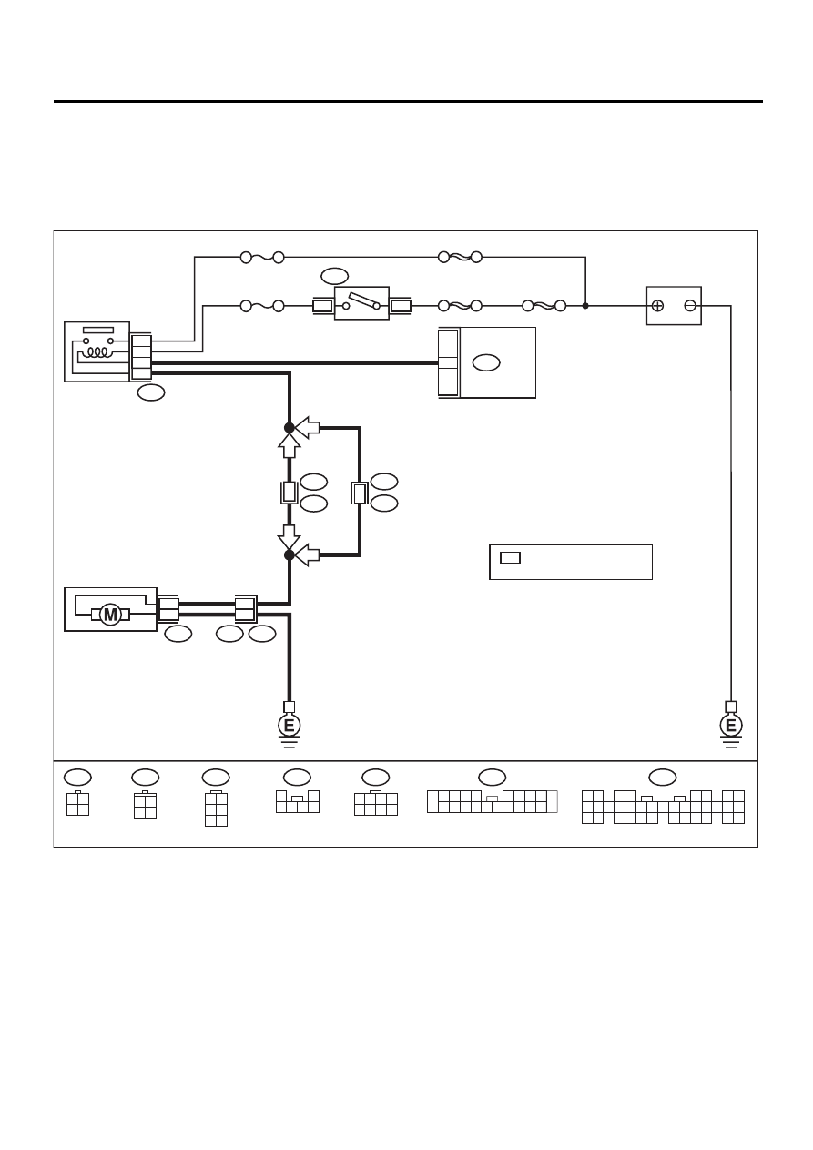
• WIRING DIAGRAM:
EN-01048
FUEL PUMP
RELAY
SBF-4
SBF-1
SBF-5
No. 13
4
1
B46
B72
IGNITION
SWITCH
BATTERY
4
3
1
2
No. 11
B134
1 2
3 4
5 6
7 8
9 10 11 12 13 14 15 16 17 18 19 20 21 22 23
24 25
26 27 28 29
30 31 32 33
34 35
B46
B97
B72
R3
R58
1
2
3 4 5 6
R57
3
5
2
1
R57
R15
FUEL PUMP
R58
*
B134
ECM
WITH IMMOBILIZER
LHD
LHD
1
R3
B99
B97
R1
3
RHD
RHD
3 4
1 2
1 2
3 4
5 6
1 2 3 4
5 6 7 8
1
2 3 4 5
6 7
9
8
10
11 12 13 14 15 16 17 18 19 20
WITHOUT IMMOBILIZER
: 29
: 16
*
3 4
1 2

EN(H4SOw/oOBD)-51
ENGINE (DIAGNOSTICS)
DIAGNOSTICS FOR ENGINE STARTING FAILURE
Step
Value
Yes
No
1
CHECK OPERATING SOUND OF FUEL
PUMP.
Make sure that fuel pump is in operation for
two seconds when turning ignition switch to
ON.
NOTE:
Fuel pump operation check can also be execut-
ed using Subaru Select Monitor. For the proce-
dure, refer to the “COMPULSORY VALVE
OPERATION CHECK MODE”.<Ref. to
EN(H4SOw/oOBD)-29, OPERATION, Compul-
sory Valve Operation Check Mode.>
Does fuel pump produce operating sound?
Fuel pump produces operating
sound.
Check fuel injec-
tor circuit. <Ref. to
EN(H4SOw/
oOBD)-53, FUEL
INJECTOR CIR-
CUIT, Diagnostics
for Engine Start-
ing Failure.>
2
CHECK GROUND CIRCUIT OF FUEL PUMP.
1) Turn ignition switch to OFF.
2) Raise rear seat, and turn floor mat up.
3) Remove service hole cover.
4) Disconnect connector from fuel pump.
5) Measure resistance of harness connector
between fuel pump and chassis ground.
Connector & terminal
(R58) No. 1 — Chassis ground:
Is the measured value less than the speci-
fied value?
5
Ω
Repair harness
and connector.
NOTE:
In this case, repair
the following:
• Open circuit in
harness between
fuel pump connec-
tor and chassis
grounding terminal
• Poor contact in
coupling connector
(R57) and (R1)
3
CHECK POWER SUPPLY TO FUEL PUMP.
1) Turn ignition switch to ON.
2) Measure voltage of power supply circuit
between fuel pump connector and chassis
ground.
Connector & terminal
(R58) No. 2 (+) — Chassis ground (
−−−−
):
Does the measured value exceed the spec-
ified value?
10 V
Replace fuel
pump.
4
CHECK HARNESS BETWEEN FUEL PUMP
AND FUEL PUMP RELAY CONNECTOR.
1) Turn ignition switch to OFF.
2) Measure resistance of harness between
fuel pump and fuel pump relay connector.
Connector & terminal
(R58) No. 2 — (B46) No. 4:
Is the measured value less than the speci-
fied value?
1
Ω
Repair harness
and connector.
NOTE:
In this case, repair
the following:
• Open circuit in
harness between
fuel pump and fuel
pump relay con-
nector
• Poor contact in
coupling connec-
tors (R57) and
(R1)
5
CHECK HARNESS BETWEEN FUEL PUMP
AND FUEL PUMP RELAY CONNECTOR.
Measure resistance of harness between fuel
pump and fuel pump relay connector.
Connector & terminal
(R58) No. 2 — Chassis ground:
Does the measured value exceed the specified
value?
1 M
Ω
Repair ground
short circuit in har-
ness between fuel
pump and fuel
pump relay con-
nector.

EN(H4SOw/oOBD)-52
ENGINE (DIAGNOSTICS)
DIAGNOSTICS FOR ENGINE STARTING FAILURE
6
CHECK FUEL PUMP RELAY.
1) Disconnect connector from fuel pump relay.
2) Remove fuel pump relay from bracket.
3) Connect battery to fuel pump relay connec-
tor terminals No. 1 and No. 3.
4) Measure resistance between connector ter-
minals of fuel pump relay.
Terminals
No. 2 — No. 4:
Is the measured value less than the speci-
fied value?
10
Ω
Replace fuel pump
relay.
7
CHECK HARNESS BETWEEN ECM AND
FUEL PUMP RELAY CONNECTOR.
1) Disconnect connectors from ECM.
2) Measure resistance of harness between
ECM and fuel pump relay connector.
Connector & terminal
With cruise control:
(B134) No. 29 — (B46) No. 3:
Without cruise control:
(B134) No. 16 — (B46) No. 3:
Is the measured value less than the speci-
fied value?
1
Ω
Repair open circuit
in harness
between ECM and
fuel pump relay
connector.
8
CHECK POOR CONTACT.
Check poor contact in ECM connector.
Is there poor contact in ECM connector?
There is poor contact.
Repair poor con-
tact in ECM con-
nector.
Check fuel injec-
tor circuit. <Ref. to
EN(H4SOw/
oOBD)-53, FUEL
INJECTOR CIR-
CUIT, Diagnostics
for Engine Start-
ing Failure.>
Step
Value
Yes
No
EN(H4SOw/oOBD)-53
ENGINE (DIAGNOSTICS)
DIAGNOSTICS FOR ENGINE STARTING FAILURE
F: FUEL INJECTOR CIRCUIT
CAUTION:
• Check or repair only faulty parts.
• After repair or replacement of faulty parts, conduct CLEAR MEMORY and INSPECTION MODES.
<Ref. to EN(H4SOw/oOBD)-28, OPERATION, Clear Memory Mode.> and <Ref. to EN(H4SOw/oOBD)-
26, OPERATION, Inspection Mode.>
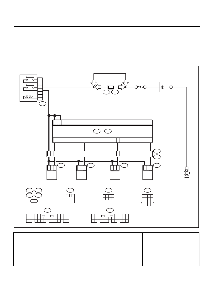
• WIRING DIAGRAM:
Step
Value
Yes
No
1
CHECK OPERATION OF EACH FUEL INJEC-
TOR.
While cranking the engine, check that each
fuel injector emits “operating” sound. Use a
sound scope or attach a screwdriver to injector
for this check.
Is the fuel injector emits “operating” sound?
Fuel injector emits “operating”
sound.
Check fuel pres-
sure. <Ref. to
ME(H4SO)-28,
INSPECTION,
Fuel Pressure.>
EN-01049
B22
1 2 3 4
5 6 7 8
9 10 11 12
13 14 15 16
E6
E17
E5
E16
1 2
1
2
1
2
1
2
1
2
A14
A13
A4
A15
9
1
10
11
12
ECM
B136
C:
B134
A:
E5
E16
E6
E17
B22
E3
FUEL INJECTOR
No. 1
FUEL INJECTOR
No. 2
FUEL INJECTOR
No. 3
FUEL INJECTOR
No. 4
BATTERY
C1
C2
A: B134
1 2
3 4
5 6
7 8
9 10 11 12 13 14 15 16 17 18 19 20 21 22 23
24 25
26 27 28 29
30 31 32 33
34 35
F44
B61
SBF-5
6
LHD
LHD
RHD
RHD
B47
MAIN RELAY
1
2
3
5
4
6
B47
3
4
1
2
5
6
F44
1 2 3 4
5 6 7 8
5
4
6 7
8
2
1
9
3
10
22
23
11 12 13 14 15
24 25
26 27
16 17 18
28 29
19 20
21
30
B136
C:
Нет комментариевНе стесняйтесь поделиться с нами вашим ценным мнением.
Текст