Subaru Legacy III (2000-2003 year). Service manual — part 359

EN(H6DO)-238
ENGINE (DIAGNOSTICS)
DIAGNOSTIC PROCEDURE WITH DIAGNOSTIC TROUBLE CODE (DTC)
BB:DTC P0461 — FUEL LEVEL SENSOR CIRCUIT RANGE/PERFORMANCE —
• DTC DETECTING CONDITION:
• Two consecutive driving cycles with fault
CAUTION:
After repair or replacement of faulty parts, conduct Clear Memory Mode <Ref. to EN(H6DO)-54, OP-
ERATION, Clear Memory Mode.> and Inspection Mode <Ref. to EN(H6DO)-47, OPERATION, Inspec-
tion Mode.>.
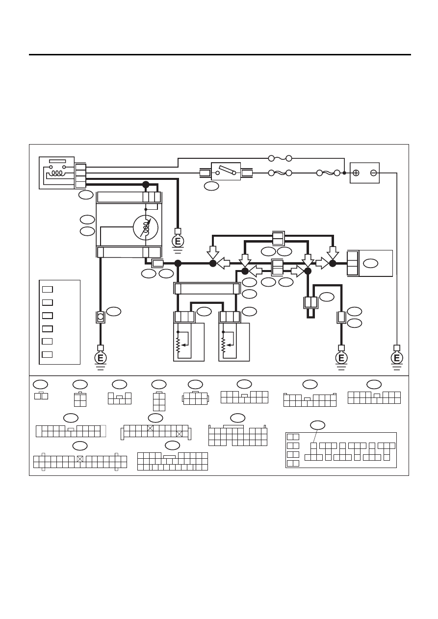
• WIRING DIAGRAM:
EN-01093
R59
R58
B72
R57
1
2
3 4 5 6
1 2
3 4
5 6
i11
1 2 3 4
5 6 7
8 9 10 11 12 13 14 15 16
B252
R3
1
2 3 4 5
6 7
9
8
10
11 12 13 14 15 16 17 18 19 20
i10
1 2 3 4 5 6 7
8 9 10 11 12 13 14
15 16 17 18 19 20 21 22 23 24 25 26 27 28 29 30
B83
B157
10
11 12 13
14 15 16
17
18
19
20
21 22 23
24 25 26
27
28
29
30
31 32 33
34 35 36
37
38
1
9
3
5
7
2
4
6
8
BATTERY
1
2
FUEL SUB
LEVEL SENSOR
FUEL SUB
METER UNIT
6
3
FUEL LEVEL
SENSOR
i53
B157
R98
R15
R57
B252
B135
R58
13
15
B83
R59
E49
R3
B99
i28
2
B5
B7
A8
6
2
29
30
25
4
1
B72
IGNITION
SWITCH
ECM
i10
i11
COMBINATION
METER
A:
B:
IGNITION
RELAY
NO. 5
SBF-4
SBF-1
1
2
1 2 3 4
5 6 7 8
B135
5 6
7 8
2
1
9
4
3
10
24
22
23
25
11 12 13 14 15
26 27 28
16 17 18 19
20 21
17
6
R3
B99
LHD : 9
RHD : 38
LHD : 13
RHD : 36
LHD : 11
RHD : 34
LHD : 10
RHD : 37
LHD : B15
RHD : A17
LHD
RHD
LHD
RHD
RHD
LHD
LHD
RHD
3 4
1 2
1 2 3 4
5 6 7 8 9 10
11 12
19
20
13 14 15 16 17 18
1
*
2
*
3
*
4
*
5
*
LHD : 12
RHD : 14
6
*
1
*
2
*
3
*
4
*
5
*
6
*
:LHD
R98
1 2 3
4 5 6
7 8 9 10 11 12 13 14
:RHD
R98
1 2 3
4 5 6 7
8 9 10 11 12 13 14 15 16
21
9
32
B99
1 2 3 4
5 6
10 11 12 13 14 15
7
16
23
30
19 20
22
26 27 28 29
8
17
24
31
18
25
EN(H6DO)-239
ENGINE (DIAGNOSTICS)
DIAGNOSTIC PROCEDURE WITH DIAGNOSTIC TROUBLE CODE (DTC)
Step
Value
Yes
No
1
CHECK ANY OTHER DTC ON DISPLAY.
Is any other DTC displayed?
Another DTC is displayed.
Inspect the rele-
vant DTC using
“List of Diagnostic
Trouble Code
(DTC)”. <Ref. to
EN(H6DO)-89, List
of Diagnostic
Trouble Code
(DTC).>
NOTE:
In this case, it is
not necessary to
inspect this trou-
ble.
Replace fuel level
sensor <Ref. to
FU(H6DO)-67,
Fuel Level Sen-
sor.> and fuel sub
level sensor <Ref.
to FU(H6DO)-68,
Fuel Sub Level
Sensor.>.
EN(H6DO)-240
ENGINE (DIAGNOSTICS)
DIAGNOSTIC PROCEDURE WITH DIAGNOSTIC TROUBLE CODE (DTC)
BC:DTC P0462 — FUEL LEVEL SENSOR CIRCUIT LOW INPUT —
• DTC DETECTING CONDITION:
• Two consecutive driving cycles with fault
CAUTION:
After repair or replacement of faulty parts, conduct Clear Memory Mode <Ref. to EN(H6DO)-54, OP-
ERATION, Clear Memory Mode.> and Inspection Mode <Ref. to EN(H6DO)-47, OPERATION, Inspec-
tion Mode.>.
• WIRING DIAGRAM:
EN-01093
R59
R58
B72
R57
1
2
3 4 5 6
1 2
3 4
5 6
i11
1 2 3 4
5 6 7
8 9 10 11 12 13 14 15 16
B252
R3
1
2 3 4 5
6 7
9
8
10
11 12 13 14 15 16 17 18 19 20
i10
1 2 3 4 5 6 7
8 9 10 11 12 13 14
15 16 17 18 19 20 21 22 23 24 25 26 27 28 29 30
B83
B157
10
11 12 13
14 15 16
17
18
19
20
21 22 23
24 25 26
27
28
29
30
31 32 33
34 35 36
37
38
1
9
3
5
7
2
4
6
8
BATTERY
1
2
FUEL SUB
LEVEL SENSOR
FUEL SUB
METER UNIT
6
3
FUEL LEVEL
SENSOR
i53
B157
R98
R15
R57
B252
B135
R58
13
15
B83
R59
E49
R3
B99
i28
2
B5
B7
A8
6
2
29
30
25
4
1
B72
IGNITION
SWITCH
ECM
i10
i11
COMBINATION
METER
A:
B:
IGNITION
RELAY
NO. 5
SBF-4
SBF-1
1
2
1 2 3 4
5 6 7 8
B135
5 6
7 8
2
1
9
4
3
10
24
22
23
25
11 12 13 14 15
26 27 28
16 17 18 19
20 21
17
6
R3
B99
LHD : 9
RHD : 38
LHD : 13
RHD : 36
LHD : 11
RHD : 34
LHD : 10
RHD : 37
LHD : B15
RHD : A17
LHD
RHD
LHD
RHD
RHD
LHD
LHD
RHD
3 4
1 2
1 2 3 4
5 6 7 8 9 10
11 12
19
20
13 14 15 16 17 18
1
*
2
*
3
*
4
*
5
*
LHD : 12
RHD : 14
6
*
1
*
2
*
3
*
4
*
5
*
6
*
:LHD
R98
1 2 3
4 5 6
7 8 9 10 11 12 13 14
:RHD
R98
1 2 3
4 5 6 7
8 9 10 11 12 13 14 15 16
21
9
32
B99
1 2 3 4
5 6
10 11 12 13 14 15
7
16
23
30
19 20
22
26 27 28 29
8
17
24
31
18
25

EN(H6DO)-241
ENGINE (DIAGNOSTICS)
DIAGNOSTIC PROCEDURE WITH DIAGNOSTIC TROUBLE CODE (DTC)
Step
Value
Yes
No
1
CHECK SPEEDOMETER AND TACHOME-
TER OPERATION IN COMBINATION
METER.
Does speedometer and tachometer operate
normally?
Operates properly.
Repair or replace
combination
meter. <Ref. to
IDI-14, Combina-
tion Meter Assem-
bly.>
2
CHECK INPUT SIGNAL FOR ECM.
1) Turn ignition switch to ON. (Engine OFF)
2) Measure voltage between ECM connector
and chassis ground.
Connector & terminal
(B135) No. 25 (+) — Chassis ground (
−−−−
):
Is the measured value less than the speci-
fied value?
0.12 V
3
CHECK INPUT SIGNAL FOR ECM. (USING
SUBARU SELECT MONITOR.)
Read data of fuel level sensor signal using
Subaru Select Monitor.
Does the value change less than the specified
value by shaking harness and connector of
ECM while monitoring the value with Subaru
Select Monitor?
NOTE:
• Subaru Select Monitor
For detailed operation procedure, refer to the
“READ CURRENT DATA FOR ENGINE”.
<Ref. to EN(H6DO)-34, Subaru Select Moni-
tor.>
0.12 V
Repair poor con-
tact in ECM con-
nector.
Even if MI lights
up, the circuit has
returned to a nor-
mal condition at
this time. A tempo-
rary poor contact
of the connector
may be the cause.
NOTE:
In this case, repair
the following:
• Poor contact in
combination meter
connector
• Poor contact in
ECM connector
• Poor contact in
coupling connec-
tors
4
CHECK INPUT VOLTAGE OF ECM.
1) Turn ignition switch to OFF.
2) Separate fuel tank cord connector (R57)
and rear wiring harness connector (R15).
3) Turn ignition switch to ON.
4) Measure voltage of harness between ECM
connector and chassis ground.
Connector & terminal
(B135) No. 25 (+) — Chassis ground (
−−−−
):
Does the measured value exceed the spec-
ified value?
0.12 V
5
CHECK HARNESS BETWEEN ECM AND
COMBINATION METER.
1) Turn ignition switch to OFF.
2) Disconnect connector from connector (i10)
and ECM connector.
3) Measure resistance between ECM and
chassis ground.
Connector & terminal
(B135) No. 25 — Chassis ground:
Does the measured value exceed the spec-
ified value?
1 M
Ω
Repair ground
short circuit in har-
ness between
ECM and combi-
nation meter con-
nector.
Нет комментариевНе стесняйтесь поделиться с нами вашим ценным мнением.
Текст