Subaru Legacy III (2000-2003 year). Service manual — part 360

EN(H6DO)-242
ENGINE (DIAGNOSTICS)
DIAGNOSTIC PROCEDURE WITH DIAGNOSTIC TROUBLE CODE (DTC)
6
CHECK HARNESS BETWEEN ECM AND
COMBINATION METER.
Measure resistance between ECM and combi-
nation meter connector.
Connector & terminal
LHD
(B135) No. 25 — (i10) No. 15:
RHD
(B135) No. 25 — (i10) No. 17:
Is the measured value less than the specified
value?
10
Ω
Repair or replace
combination
meter. <Ref. to
IDI-14, Combina-
tion Meter Assem-
bly.>
Repair open circuit
between ECM and
combination meter
connector.
NOTE:
In this case, repair
the following:
Poor contact in
coupling connector
7
CHECK FUEL TANK CORD.
1) Turn ignition switch to OFF.
2) Disconnect connector from fuel sub level
sensor.
3) Measure resistance between fuel sub level
sensor and chassis ground.
Connector & terminal
(R59) No. 1 — Chassis ground:
Does the measured value exceed the spec-
ified value?
1 M
Ω
Repair ground
short circuit in fuel
tank cord.
8
CHECK FUEL TANK CORD.
1) Disconnect connector from fuel pump
assembly.
2) Measure resistance between fuel pump
assembly and chassis ground.
Connector & terminal
(R59) No. 2 — Chassis ground:
Does the measured value exceed the spec-
ified value?
1 M
Ω
Repair ground
short circuit in fuel
tank cord.
9
CHECK FUEL LEVEL SENSOR.
1) Remove fuel pump assembly. <Ref. to
2) Measure resistance between fuel level sen-
sor and terminals with its float set to the full
position.
Terminals
No. 3 — No. 6:
Is the measured value within the specified
range?
0.5 — 2.5
Ω
Replace fuel level
sensor.
10
CHECK FUEL SUB LEVEL SENSOR.
Warning:
During work procedures, if fuel tank is more
than 3/4 full, be careful because fuel may
spill.
1) Remove fuel sub level sensor. <Ref. to
FU(H6DO)-68, Fuel Sub Level Sensor.>
2) Measure resistance between fuel sub level
sensor and terminals with its float set to the
full position.
Terminals
No. 1 — No. 2:
Is the measured value within the specified
range?
0.5 — 2.5
Ω
Repair poor con-
tact in harness
between ECM and
combination meter
connector.
Replace fuel sub
level sensor.
Step
Value
Yes
No
EN(H6DO)-243
ENGINE (DIAGNOSTICS)
DIAGNOSTIC PROCEDURE WITH DIAGNOSTIC TROUBLE CODE (DTC)
MEMO:
EN(H6DO)-244
ENGINE (DIAGNOSTICS)
DIAGNOSTIC PROCEDURE WITH DIAGNOSTIC TROUBLE CODE (DTC)
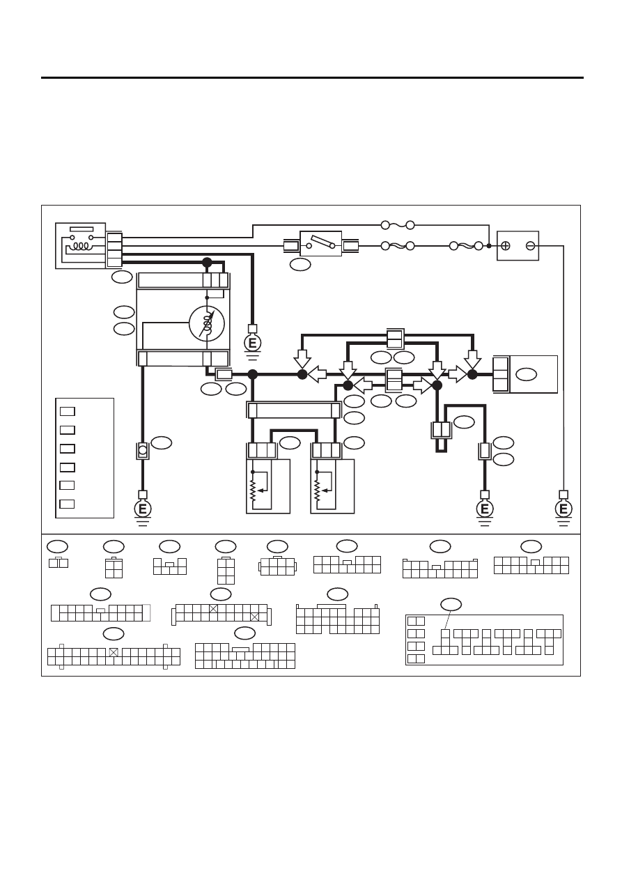
BD:DTC P0463 — FUEL LEVEL SENSOR CIRCUIT HIGH INPUT —
• DTC DETECTING CONDITION:
• Two consecutive driving cycles with fault
CAUTION:
After repair or replacement of faulty parts, conduct Clear Memory Mode <Ref. to EN(H6DO)-54, OP-
ERATION, Clear Memory Mode.> and Inspection Mode <Ref. to EN(H6DO)-47, OPERATION, Inspec-
tion Mode.>.
• WIRING DIAGRAM:
EN-01093
R59
R58
B72
R57
1
2
3 4 5 6
1 2
3 4
5 6
i11
1 2 3 4
5 6 7
8 9 10 11 12 13 14 15 16
B252
R3
1
2 3 4 5
6 7
9
8
10
11 12 13 14 15 16 17 18 19 20
i10
1 2 3 4 5 6 7
8 9 10 11 12 13 14
15 16 17 18 19 20 21 22 23 24 25 26 27 28 29 30
B83
B157
10
11 12 13
14 15 16
17
18
19
20
21 22 23
24 25 26
27
28
29
30
31 32 33
34 35 36
37
38
1
9
3
5
7
2
4
6
8
BATTERY
1
2
FUEL SUB
LEVEL SENSOR
FUEL SUB
METER UNIT
6
3
FUEL LEVEL
SENSOR
i53
B157
R98
R15
R57
B252
B135
R58
13
15
B83
R59
E49
R3
B99
i28
2
B5
B7
A8
6
2
29
30
25
4
1
B72
IGNITION
SWITCH
ECM
i10
i11
COMBINATION
METER
A:
B:
IGNITION
RELAY
NO. 5
SBF-4
SBF-1
1
2
1 2 3 4
5 6 7 8
B135
5 6
7 8
2
1
9
4
3
10
24
22
23
25
11 12 13 14 15
26 27 28
16 17 18 19
20 21
17
6
R3
B99
LHD : 9
RHD : 38
LHD : 13
RHD : 36
LHD : 11
RHD : 34
LHD : 10
RHD : 37
LHD : B15
RHD : A17
LHD
RHD
LHD
RHD
RHD
LHD
LHD
RHD
3 4
1 2
1 2 3 4
5 6 7 8 9 10
11 12
19
20
13 14 15 16 17 18
1
*
2
*
3
*
4
*
5
*
LHD : 12
RHD : 14
6
*
1
*
2
*
3
*
4
*
5
*
6
*
:LHD
R98
1 2 3
4 5 6
7 8 9 10 11 12 13 14
:RHD
R98
1 2 3
4 5 6 7
8 9 10 11 12 13 14 15 16
21
9
32
B99
1 2 3 4
5 6
10 11 12 13 14 15
7
16
23
30
19 20
22
26 27 28 29
8
17
24
31
18
25

EN(H6DO)-245
ENGINE (DIAGNOSTICS)
DIAGNOSTIC PROCEDURE WITH DIAGNOSTIC TROUBLE CODE (DTC)
Step
Value
Yes
No
1
CHECK SPEEDOMETER AND TACHOME-
TER OPERATION IN COMBINATION
METER.
Does speedometer and tachometer operate
normally?
Operates properly.
Repair or replace
combination
meter. <Ref. to
IDI-14, Combina-
tion Meter Assem-
bly.>
2
CHECK INPUT SIGNAL FOR ECM.
1) Turn ignition switch to ON. (Engine OFF)
2) Measure voltage between ECM connector
and chassis ground.
Connector & terminal
(B135) No. 25 (+) — Chassis ground (
−−−−
):
Does the measured value exceed the spec-
ified value?
4.75 V
Even if MI lights
up, the circuit has
returned to a nor-
mal condition at
this time. A tempo-
rary poor contact
of the connector
may be the cause.
NOTE:
In this case, repair
the following:
• Poor contact in
fuel pump connec-
tor
• Poor contact in
coupling connector
3
CHECK INPUT VOLTAGE OF ECM.
1) Turn ignition switch to OFF.
2) Disconnect combination meter connector
(i10) and ECM connector.
3) Turn ignition switch to ON.
4) Measure voltage of harness between ECM
and chassis ground.
Connector & terminal
(B135) No. 25 (+) — Chassis ground (
−−−−
):
Does the measured value exceed the spec-
ified value?
4.75 V
Repair battery
short circuit
between ECM and
combination meter
connector.
4
CHECK HARNESS BETWEEN ECM AND
FUEL TANK CORD.
1) Turn ignition switch to OFF.
2) Separate fuel tank cord connector (R57)
and rear wiring harness connector (R15).
3) Measure resistance between ECM and fuel
tank cord.
Connector & terminal
(B135) No. 25 — (R15) No. 2:
Is the measured value less than the speci-
fied value?
5
Ω
Repair open circuit
between ECM and
fuel tank cord.
5
CHECK HARNESS BETWEEN FUEL TANK
CORD AND CHASSIS GROUND.
Measure resistance between fuel tank cord
and chassis ground.
Connector & terminal
(R15) No. 6 — Chassis ground:
Is the measured value less than the specified
value?
5
Ω
Repair open circuit
between fuel tank
cord and chassis
ground.
NOTE:
In this case, repair
the following:
Poor contact in
coupling connec-
tors
Нет комментариевНе стесняйтесь поделиться с нами вашим ценным мнением.
Текст