Subaru Legacy III (2000-2003 year). Service manual — part 357
EN(H6DO)-230
ENGINE (DIAGNOSTICS)
DIAGNOSTIC PROCEDURE WITH DIAGNOSTIC TROUBLE CODE (DTC)
AY:DTC P0420 — CATALYST SYSTEM EFFICIENCY BELOW THRESHOLD
(BANK 1) —
• DTC DETECTING CONDITION:
• Two consecutive driving cycles with fault
• TROUBLE SYMPTOM:
• Engine stalls.
• Idle mixture is out of specifications.
CAUTION:
After repair or replacement of faulty parts, conduct Clear Memory Mode <Ref. to EN(H6DO)-54, OP-
ERATION, Clear Memory Mode.> and Inspection Mode <Ref. to EN(H6DO)-47, OPERATION, Inspec-
tion Mode.>.
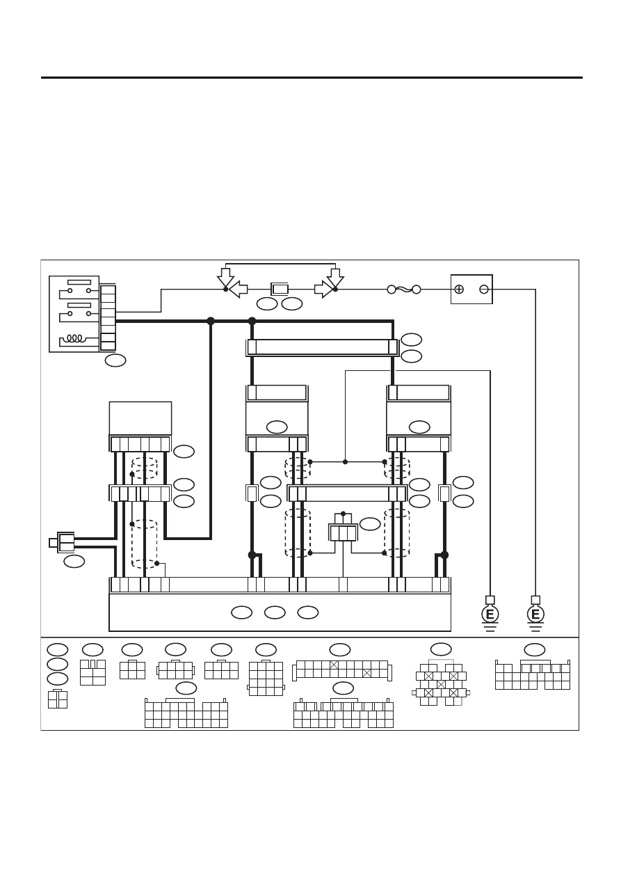
• WIRING DIAGRAM:
EN-01091
BATTERY
B22
E3
B47
MAIN RELAY
1
2
3
5
4
6
F44
1 2 3 4
5 6 7 8
D4
D5
D18
D29
D19
D20
D30
D7
D6
2
4
1
3
2
1
3
4
FRONT OXYGEN
(A/F) SENSOR RH
E47
FRONT OXYGEN
(A/F) SENSOR LH
E24
B19
B17
C13
B26
REAR
OXYGEN
SENSOR
5
4
6
2
4
3
1
3
2
B83
B19
T5
B21
E2
B83
T6
5
7
ECM
B136
C:
B135
B:
B137
D:
B47
3
4
1
2
5
6
B135
B136
C:
B:
B252
E24
E47
B83
2
3
19
20
11
8
3
1
2
E49
B252
4
E49
B252
8
B19
1
3
4 5 6
2
1 2 3 4
5 6 7 8
T6
3
4
1
2
B22
1 2 3 4
5 6 7 8
9 10 11 12
13 14 15 16
B137
D:
1
2
7
8
9
5
6
3
4
10 11 12
19 20 21
29 30 31
13 14 15 16 17
27 28
18
22 23 24 25 26
1 2
7
8 9
5
6
3
4
10 11 12
19 20 21
13 14 15 16
17 18
22 23 24
5 6
7 8
2
1
9
4
3
10
24
22
23
25
11 12 13 14 15
26 27 28
16 17 18 19
20 21
1 2 3 4
5 6 7 8 9 10
11 12
19 20
13 14 15 16 17 18
SBF-5
F44
B61
6
RHD
LHD
LHD
RHD
B21
1 2
5
6 7
8
13
14 15
16
9 10
11 12
3 4
17 18
19 20

EN(H6DO)-231
ENGINE (DIAGNOSTICS)
DIAGNOSTIC PROCEDURE WITH DIAGNOSTIC TROUBLE CODE (DTC)
Step
Value
Yes
No
1
CHECK ANY OTHER DTC ON DISPLAY.
Is any other DTC displayed?
Another DTC is displayed.
Inspect the rele-
vant DTC using
“List of Diagnostic
Trouble Code
(DTC)”. <Ref. to
EN(H6DO)-89, List
of Diagnostic
Trouble Code
(DTC).>
NOTE:
In this case, it is
not necessary to
inspect DTC
P0420.
2
CHECK EXHAUST SYSTEM.
Check for gas leaks or air suction caused by
loose or dislocated nuts and bolts, and open
hole at exhaust pipes.
NOTE:
Check the following positions.
• Between cylinder head and front exhaust
pipe
• Between front exhaust pipe and front catalytic
converter
• Between front catalytic converter and rear
catalytic converter
Is there a fault in exhaust system?
There is a malfunction.
Repair or replace
exhaust system.
3
CHECK REAR CATALYTIC CONVERTER.
Separate rear catalytic converter from rear
exhaust pipe.
Is there damage at rear face of rear catalyst?
There is damage.
Replace front cat-
alytic converter
<Ref. to
EC(H6DO)-3,
Front Catalytic
Converter.> and
rear catalytic con-
verter <Ref. to
EC(H6DO)-6,
Rear Catalytic
Converter.>.
4
CHECK FRONT CATALYTIC CONVERTER.
Remove front catalytic converter.
Is there damage at rear face or front face of
front catalyst?
There is damage.
Replace front cat-
alytic converter.
<Ref. to
EC(H6DO)-3,
Front Catalytic
Converter.>
Contact SUBRU
distributor service.
NOTE:
Inspection by DTM
is required, be-
cause probable
cause is deteriora-
tion of multiple
parts.
EN(H6DO)-232
ENGINE (DIAGNOSTICS)
DIAGNOSTIC PROCEDURE WITH DIAGNOSTIC TROUBLE CODE (DTC)
AZ:DTC P0458 — EVAPORATIVE EMISSION CONTROL SYSTEM PURGE CON-
TROL VALVE CIRCUIT LOW —
• DTC DETECTING CONDITION:
• Two consecutive driving cycles with fault
• TROUBLE SYMPTOM:
• Erroneous idling
CAUTION:
After repair or replacement of faulty parts, conduct Clear Memory Mode <Ref. to EN(H6DO)-54, OP-
ERATION, Clear Memory Mode.> and Inspection Mode <Ref. to EN(H6DO)-47, OPERATION, Inspec-
tion Mode.>.
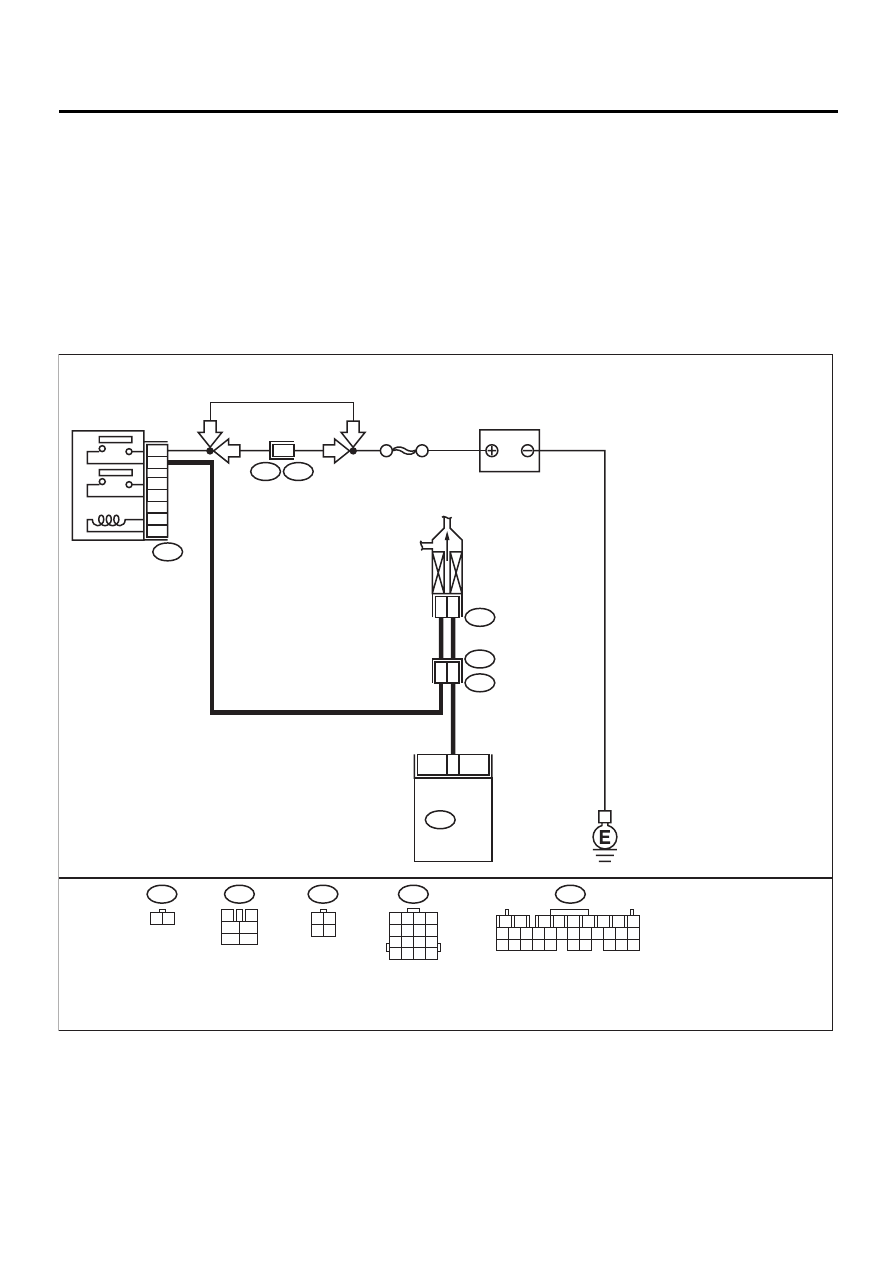
• WIRING DIAGRAM:
EN-01092
16
B20
E1
PURGE CONTROL
SOLENOID VALVE
2
1
2
2
4
E4
SBF-5
B137
B20
1 2 3 4
5 6 7 8
9 10 11 12
13 14 15 16
E4
1 2
B47
3
4
1
2
5
6
BATTERY
B137
ECM
B47
B108
F46
MAIN RELAY
2
1
3
5
4
6
1
2
7
8
9
5
6
3
4
10 11 12
19 20 21
29 30 31
13 14 15 16 17
27 28
18
22 23 24 25 26
RHD
LHD
RHD
LHD
F46
3 4
1 2

EN(H6DO)-233
ENGINE (DIAGNOSTICS)
DIAGNOSTIC PROCEDURE WITH DIAGNOSTIC TROUBLE CODE (DTC)
Step
Value
Yes
No
1
CHECK OUTPUT SIGNAL FROM ECM.
1) Turn ignition switch to ON.
2) Measure voltage between ECM and chas-
sis ground.
Connector & terminal
(B137) No. 16 (+) — Chassis ground (
−−−−
):
Does the measured value exceed the spec-
ified value?
10 V
Even if MI lights
up, the circuit has
returned to a nor-
mal condition at
this time. Contact
SUBARU distribu-
tor service.
NOTE:
Inspection by DTM
is required, be-
cause probable
cause is deteriora-
tion of multiple
parts.
2
CHECK HARNESS BETWEEN PURGE CON-
TROL SOLENOID VALVE AND ECM CON-
NECTOR.
1) Turn ignition switch to OFF.
2) Disconnect connectors from purge control
solenoid valve and ECM.
3) Measure resistance of harness between
purge control solenoid valve connector and
engine ground.
Connector & terminal
(E4) No. 2 — Engine ground:
Is the measured value less than the speci-
fied value?
10
Ω
Repair ground
short circuit in har-
ness between
ECM and purge
control solenoid
valve connector.
3
CHECK HARNESS BETWEEN PURGE CON-
TROL SOLENOID VALVE AND ECM CON-
NECTOR.
Measure resistance of harness between ECM
and purge control solenoid valve of harness
connector.
Connector & terminal
(B137) No. 16 — (E4) No. 2:
Is the measured value less than the specified
value?
1
Ω
Repair open circuit
in harness
between ECM and
purge control sole-
noid valve connec-
tor.
NOTE:
In this case, repair
the following:
• Open circuit in
harness between
ECM and purge
control solenoid
valve connector
• Poor contact in
coupling connector
4
CHECK PURGE CONTROL SOLENOID
VALVE.
1) Remove purge control solenoid valve.
2) Measure resistance between purge control
solenoid valve terminals.
Terminals
No. 1 — No. 2:
Is the measured value within the specified
range?
10 — 100
Ω
Replace purge
control solenoid
valve. <Ref. to
EC(H6DO)-8,
Purge Control
Solenoid Valve.>
Нет комментариевНе стесняйтесь поделиться с нами вашим ценным мнением.
Текст