Subaru Legacy III (2000-2003 year). Service manual — part 114
EN(H4SO)-68
ENGINE (DIAGNOSTICS)
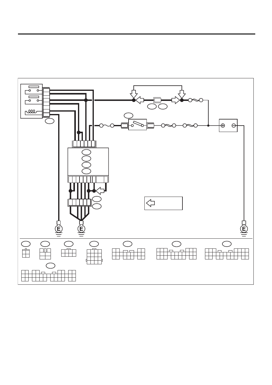
DIAGNOSTICS FOR ENGINE STARTING FAILURE
C: CONTROL MODULE POWER SUPPLY AND GROUND LINE
CAUTION:
After repair or replacement of faulty parts, conduct Clear Memory Mode<Ref. to EN(H4SO)-47, OPER-
ATION, Clear Memory Mode.> and Inspection Mode. <Ref. to EN(H4SO)-40, OPERATION, Inspection
Mode.>
• WIRING DIAGRAM:
EN-01119
F44
B61
6
RHD
RHD
B9
C21
C23
B1
C12
B2
E3
B22
A7
A35
C26
B21
D14
C19
13
15
14
16
B47
BATTERY
MAIN RELAY
1
2
3
5
6
4
SBF-5
SBF-4
SBF-1
3
1
B72
IGNITION
SWITCH
ECM
B134
A :
B135
B :
B136
C :
B137
D :
C5
8
5 6 7
8
2
1
9
4
3
10
24
22 23
25
11 12 13 14 15
26
27 28
16 17 18 19
20 21
B135
B134
1 2
3 4
5 6
7 8
9 10 11 12 13 14 15 16 17 18 19 20 21 22 23
24 25
26 27 28 29
30 31 32 33
34 35
B47
3
4
1
2
5
6
B72
3 4
1 2
B22
1 2 3 4
5 6 7 8
9 10 11 12
13 14 15 16
C16
NO. 11
1 2 3 4
5 6 7 8
F44
B136
5 6
7
2
1
9
8
4
3
23
21 22
24
10 11 12 13 14
25 26
15 16 17
18 19 20
B137
4
1
5
3
2
6
18
15
16
7 8 9 10 11
17
19 20
12 13
14
LHD
LHD
: LHD MT MODEL
*
*

EN(H4SO)-69
ENGINE (DIAGNOSTICS)
DIAGNOSTICS FOR ENGINE STARTING FAILURE
Step
Value
Yes
No
1
CHECK MAIN RELAY.
1) Turn the ignition switch to OFF.
2) Remove main relay.
3) Connect battery to main relay terminals No.
1 and No. 2.
4) Measure resistance between main relay
terminals.
Terminals
No. 3 — No. 5:
No. 4 — No. 6:
Is the measured value less than the speci-
fied value?
10
Ω
Replace main
relay.
2
CHECK GROUND CIRCUIT OF ECM.
1) Disconnect connector from ECM.
2) Measure resistance of harness between
ECM and chassis ground.
Connector & terminal
(B134) No. 7 — Chassis ground:
(B134) No. 35 — Chassis ground:
(B135) No. 21 — Chassis ground:
(B136) No. 5 — Chassis ground:
(B136) No. 16 — Chassis ground:
(B136) No. 26— Chassis ground:
(B137) No. 14 — Chassis ground:
(B136) No. 19 — Chassis ground (LHD
MT model):
Is the measured value less than the speci-
fied value?
5
Ω
Repair open circuit
in harness
between ECM
connector and
engine grounding
terminal.
3
CHECK INPUT VOLTAGE OF ECM.
Measure voltage between ECM connector and
chassis ground.
Connector & terminal
(B135) No. 9 (+) — Chassis ground (–):
(B135) No. 23 (+) — Chassis ground (–):
Does the measured value exceed the specified
value?
10 V
Repair ground
short circuit of
power supply cir-
cuit.
4
CHECK INPUT VOLTAGE OF ECM.
1) Turn ignition switch to ON.
2) Measure voltage between ECM connector
and chassis ground.
Connector & terminal
(B136) No. 21(+) — Chassis ground (–):
Does the measured value exceed the spec-
ified value?
10 V
Repair open or
ground short cir-
cuit of power sup-
ply circuit.
5
CHECK HARNESS BETWEEN ECM AND
MAIN RELAY CONNECTOR.
1) Turn ignition switch to OFF.
2) Measure resistance between ECM and
chassis ground.
Connector & terminal
(B136) No. 12 — Chassis ground:
Does the measured value exceed the spec-
ified value?
1 M
Ω
Repair ground
short circuit in har-
ness between
ECM connector
and main relay
connector.

EN(H4SO)-70
ENGINE (DIAGNOSTICS)
DIAGNOSTICS FOR ENGINE STARTING FAILURE
6
CHECK OUTPUT VOLTAGE FROM ECM.
1) Connect connector to ECM.
2) Turn ignition switch to ON.
3) Measure voltage between ECM connector
and chassis ground.
Connector & terminal
(B136) No. 12 (+) — Chassis ground (–):
Does the measured value exceed the spec-
ified value?
10 V
Replace ECM.
7
CHECK INPUT VOLTAGE OF MAIN RELAY.
Check voltage between main relay connector
and chassis ground.
Connector & terminal
(B47) No. 2 (+) — Chassis ground (–):
Does the measured value exceed the specified
value?
10 V
Repair open circuit
in harness
between ECM
connector and
main relay con-
nector.
8
CHECK GROUND CIRCUIT OF MAIN RE-
LAY.
1) Turn ignition switch to OFF.
2) Measure resistance between main relay
connector and chassis ground.
Connector & terminal
(B47) No. 1 — Chassis ground:
Is the measured value less than the speci-
fied value?
5
Ω
Repair open circuit
between main
relay and chassis
ground.
9
CHECK INPUT VOLTAGE OF MAIN RELAY.
Measure voltage between main relay connec-
tor and chassis ground.
Connector & terminal
(B47) No. 5 (+) — Chassis ground (
−−−−
):
(B47) No. 6 (+) — Chassis ground (
−−−−
):
Does the measured value exceed the specified
value?
10 V
Repair open or
ground short cir-
cuit in harness of
power supply cir-
cuit.
10
CHECK INPUT VOLTAGE OF ECM.
1) Connect main relay connector.
2) Turn ignition switch to ON.
3) Measure voltage between ECM connector
and chassis ground.
Connector & terminal
(B135) No. 1 (+) — Chassis ground (–):
(B135) No. 2 (+) — Chassis ground (–):
Does the measured value exceed the spec-
ified value?
10 V
Check ignition
control system.
<Ref. to
EN(H4SO)-72,
IGNITION CON-
TROL SYSTEM,
Diagnostics for
Engine Starting
Failure.>
Repair open or
ground short cir-
cuit in harness
between ECM
connector and
main relay con-
nector.
Step
Value
Yes
No
EN(H4SO)-71
ENGINE (DIAGNOSTICS)
DIAGNOSTICS FOR ENGINE STARTING FAILURE
MEMO:
Нет комментариевНе стесняйтесь поделиться с нами вашим ценным мнением.
Текст