Subaru Legacy III (2000-2003 year). Service manual — part 113
EN(H4SO)-64
ENGINE (DIAGNOSTICS)
DIAGNOSTICS FOR ENGINE STARTING FAILURE
B: STARTER MOTOR CIRCUIT
CAUTION:
After repair or replacement of faulty parts, conduct CLEAR MEMORY MODE<Ref. to EN(H4SO)-47,
Clear Memory Mode.> and INSPECTION MODE <Ref. to EN(H4SO)-40, Inspection Mode.> .
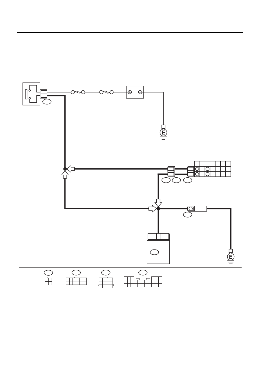
• WIRING DIAGRAM:
EN-01118
12
INHIBITOR SWITCH
STARTER
MOTOR
7
P
R
N
D
3
2
1
SBF-4
SBF-1
B14
B72
12
11
T7
T3
B12
1
3
IGNITION
SWITCH
AT
MT
AT
MT
T7
1 2 3 4 5 6
7 8 9 10 11 12
B72
3 4
1 2
20
B136
ECM
BATTERY
B12
1 2 3 4
5 6 7 8
9 10 11 12
B136
5 6
7
2
1
9
8
4
3
23
21 22
24
10 11 12 13 14
25 26
15 16 17
18 19 20

EN(H4SO)-65
ENGINE (DIAGNOSTICS)
DIAGNOSTICS FOR ENGINE STARTING FAILURE
Step
Value
Yes
No
1
CHECK OPERATION OF STARTER MOTOR.
Does the starter motor operates, when the
switch is ON?
Operates.
2
CHECK DTC.
Is DTC displayed?
DTC indicated.
Check DTC using
“List of Diagnostic
Trouble Code
(DTC)”. <Ref. to
EN(H4SO)-83, List
of Diagnostic
Trouble Code
(DTC).>
Repair poor con-
tact in ECM con-
nector.
3
CHECK INPUT SIGNAL FOR STARTER MO-
TOR.
1) Turn the ignition switch to OFF.
2) Disconnect the connector from starter
motor.
3) Turn the ignition switch to ST.
4) Measure the power supply voltage between
starter motor connector terminal and
engine ground.
Connector & terminal
(B14) No. 1 (+) — Engine ground (
−−−−
):
Is the measured value more than specified
value?
NOTE:
•On AT vehicles, place the selector lever in the
“P” or “N” position.
10 V
4
CHECK GROUND CIRCUIT OF STARTER
MOTOR.
1) Turn the ignition switch to OFF.
2) Disconnect the terminal from starter motor.
3) Measure the resistance of ground cable
between ground cable terminal and engine
ground.
Is the measured value less than specified
value?
5
Ω
Check the starter
motor. <Ref. to
SC(H4SO)-6,
Starter.>
Repair open circuit
of ground cable.
5
CHECK HARNESS BETWEEN BATTERY
AND IGNITION SWITCH CONNECTOR.
1) Disconnect the connector from ignition
switch.
2) Measure the power supply voltage between
ignition switch connector and chassis
ground.
Connector & terminal
(B72) No. 1 (+) — Chassis ground (
−−−−
):
Does the measured value exceed the spec-
ified value?
10 V
Repair open circuit
in harness
between ignition
switch and battery,
and check fuse
SBF No. 4 and
SBF No. 1.
6
CHECK IGNITION SWITCH.
1) Disconnect the connector from ignition
switch.
2) Measure the resistance between ignition
switch terminals while turning ignition
switch to the “ST” position.
Terminals
No. 1 — No. 3:
Is the measured value less than specified
value?
5
Ω
Replace the igni-
tion switch.

EN(H4SO)-66
ENGINE (DIAGNOSTICS)
DIAGNOSTICS FOR ENGINE STARTING FAILURE
7
CHECK TRANSMISSION TYPE.
Is the target AT vehicle?
Target is AT vehicle.
Repair open or
short to ground
between ignition
switch and starter
motor.
8
CHECK INPUT VOLTAGE OF INHIBITOR
SWITCH.
1) Turn the ignition switch to OFF.
2) Disconnect the connector from inhibitor
switch.
3) Connect the connector to ignition switch.
4) Measure the input voltage between inhibitor
switch connector terminal and engine
ground while turning ignition switch to ST.
Connector & terminal
(B12) No. 12 (+) — Engine ground (–):
Does the measured value exceed the spec-
ified value?
10 V
Repair open or
ground short cir-
cuit in harness
between inhibitor
switch and ignition
switch.
9
CHECK INHIBITOR SWITCH.
1) Place the selector lever in the “P” or “N”
position.
2) Measure the resistance between inhibitor
switch terminals.
Connector & terminal
(T3) No. 11 — No. 12:
Is the measured value less than specified
value?
1
Ω
Repair open or
ground short cir-
cuit in harness
between inhibitor
switch and starter
motor.
Replace the inhibi-
tor switch. <Ref. to
AT-49, Inhibitor
Switch.>
Step
Value
Yes
No
EN(H4SO)-67
ENGINE (DIAGNOSTICS)
DIAGNOSTICS FOR ENGINE STARTING FAILURE
MEMO:
Нет комментариевНе стесняйтесь поделиться с нами вашим ценным мнением.
Текст