Subaru Legacy III (2000-2003 year). Service manual — part 115
EN(H4SO)-72
ENGINE (DIAGNOSTICS)
DIAGNOSTICS FOR ENGINE STARTING FAILURE
D: IGNITION CONTROL SYSTEM
CAUTION:
After repair or replacement of faulty parts, conduct Clear Memory Mode<Ref. to EN(H4SO)-47, OPER-
ATION, Clear Memory Mode.> and Inspection Mode <Ref. to EN(H4SO)-40, OPERATION, Inspection
Mode.> .
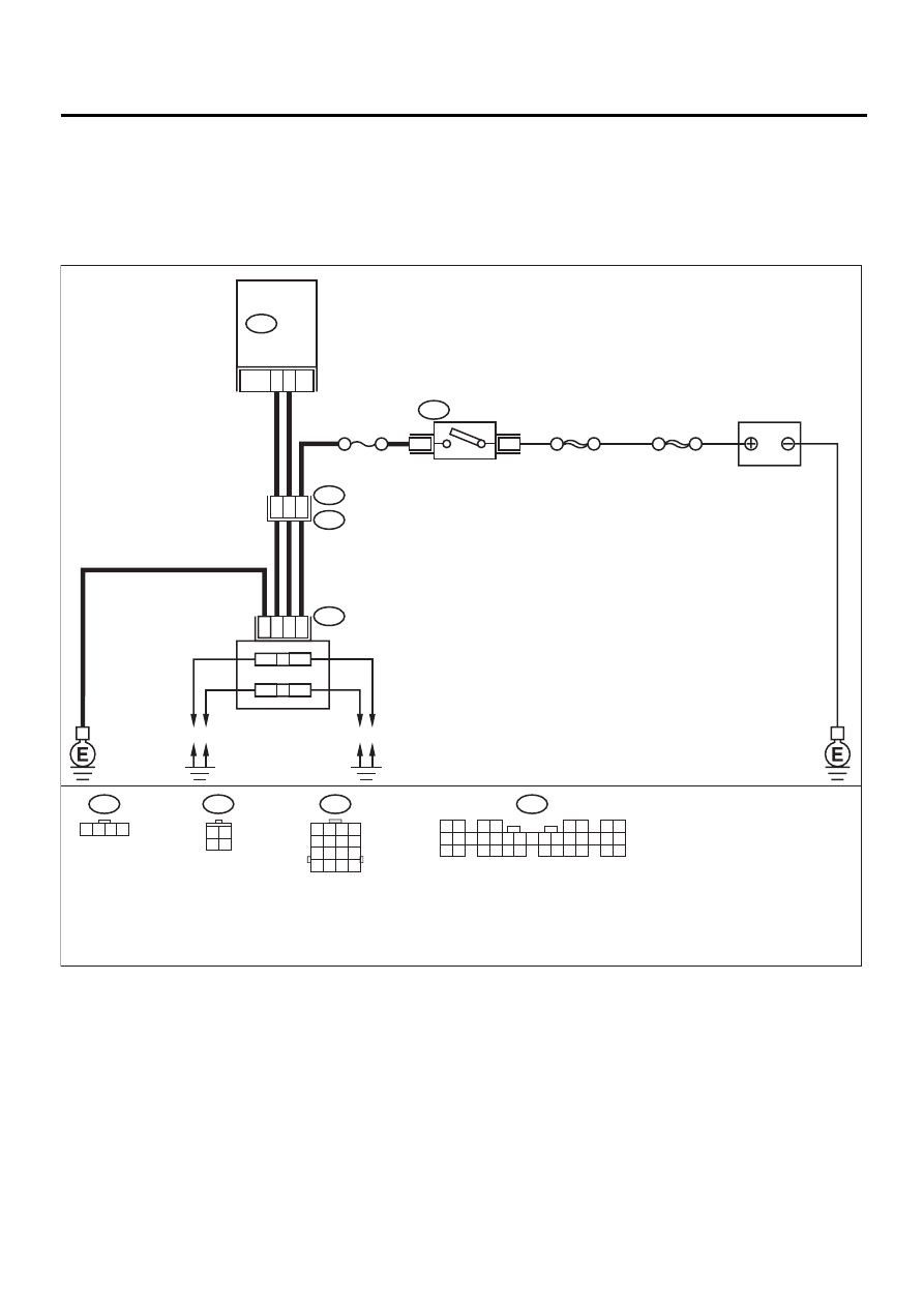
• WIRING DIAGRAM:
EN-00717
32
33
B134
B72
3 4
1 2
3 4
1 2
E12
B22
1 2 3 4
5 6 7 8
13 14 15 16
9 10 11 12
6
5
4
3
4
1
2
IGNITOR
&
IGNITION COIL ASSY
B22
E3
E12
SBF-1
SBF-4
B134
1 2
3 4
5 6
7 8
9 10 11 12 13 14 15 16 17 18 19 20 21 22 23
24 25
26 27 28 29
30 31 32 33
34 35
ECM
BATTERY
NO. 11
4
1
B72
IGNITION
SWITCH
3
4
1
2

EN(H4SO)-73
ENGINE (DIAGNOSTICS)
DIAGNOSTICS FOR ENGINE STARTING FAILURE
Step
Value
Yes
No
1
CHECK SPARK PLUG CONDITION.
1) Remove the spark plug. <Ref. to
IG(H4SO)-5, REMOVAL, Spark Plug.>
2) Check the spark plug condition. <Ref. to
IG(H4SO)-6, INSPECTION, Spark Plug.>
Is the spark plug's status OK?
OK
Replace the spark
plug.
2
CHECK IGNITION SYSTEM FOR SPARKS.
1) Remove plug cord cap from each spark
plug.
2) Install new spark plug on plug cord cap.
CAUTION:
Do not remove spark plug from engine.
3) Contact spark plug's thread portion on
engine.
4) While opening throttle valve fully, crank
engine to check that spark occurs at each
cylinder.
Does spark occur at each cylinder?
Spark occurs.
Check fuel pump
system. <Ref. to
EN(H4SO)-76,
FUEL PUMP CIR-
CUIT, Diagnostics
for Engine Start-
ing Failure.>
3
CHECK POWER SUPPLY CIRCUIT FOR IG-
NITION COIL & IGNITOR ASSEMBLY.
1) Turn ignition switch to OFF.
2) Disconnect connector from ignition coil &
ignitor assembly.
3) Turn ignition switch to ON.
4) Measure power supply voltage between
ignition coil & ignitor assembly connector
and engine ground.
Connector & terminal
(E12) No. 2 (+) — Engine ground (
−−−−
):
Does the measured value exceed the spec-
ified value?
10 V
Repair harness
and connector.
NOTE:
In this case, repair
the following:
• Open circuit in
harness between
ignition coil & igni-
tor assembly, and
ignition switch
connector
• Poor contact in
coupling connec-
tors
4
CHECK HARNESS OF IGNITION COIL & IG-
NITOR ASSEMBLY GROUND CIRCUIT.
1) Turn ignition switch to OFF.
2) Measure resistance between ignition coil &
ignitor assembly connector and engine
ground.
Connector & terminal
(E12) No. 3 — Engine ground:
Is the measured value less than the speci-
fied value?
5
Ω
Repair harness
and connector.
NOTE:
In this case, repair
the following:
• Open circuit in
harness between
ignition coil & igni-
tor assembly con-
nector and engine
grounding terminal
5
CHECK IGNITION COIL & IGNITOR ASSEM-
BLY.
1) Remove spark plug cords.
2) Measure resistance between spark plug
cord contact portions to check secondary
coil.
Terminals
No. 1 — No. 2:
No. 3 — No. 4:
Is the measured value within the specified
range?
10 - 15 k
Ω
Replace ignition
coil & ignitor
assembly. <Ref. to
IG(H4SO)-8, Igni-
tion Coil and Igni-
tor Assembly.>

EN(H4SO)-74
ENGINE (DIAGNOSTICS)
DIAGNOSTICS FOR ENGINE STARTING FAILURE
6
CHECK INPUT SIGNAL FOR IGNITION COIL
& IGNITOR ASSEMBLY.
1) Connect connector to ignition coil & ignitor
assembly.
2) Check if voltage varies synchronously with
engine speed when cranking, while moni-
toring voltage between ignition coil & ignitor
assembly connector and engine ground.
Connector & terminal
(E12) No. 1 (+) — Engine ground (–):
(E12) No. 4 (+) — Engine ground (–):
Does the measured value exceed the spec-
ified value?
10 V
Replace ignition
coil & ignitor
assembly. <Ref. to
IG(H4SO)-8, Igni-
tion Coil and Igni-
tor Assembly.>
7
CHECK HARNESS BETWEEN ECM AND IG-
NITION COIL & IGNITOR ASSEMBLY CON-
NECTOR.
1) Turn ignition switch to OFF.
2) Disconnect connector from ECM.
3) Disconnect connector from ignition coil &
ignitor assembly.
4) Measure resistance of harness between
ECM and ignition coil & ignitor assembly
connector.
Connector & terminal
(B134) No. 33 — (E12) No. 1:
(B134) No. 32 — (E12) No. 4:
Is the measured value less than the speci-
fied value?
1
Ω
Repair harness
and connector.
NOTE:
In this case, repair
the following:
• Open circuit in
harness between
ECM and ignition
coil & ignitor
assembly connec-
tor
• Poor contact in
coupling connector
8
CHECK HARNESS BETWEEN ECM AND IG-
NITION COIL & IGNITOR ASSEMBLY CON-
NECTOR.
Measure resistance of harness between ECM
and engine ground.
Connector & terminal:
(B134) No. 32 — Engine ground:
(B134) No. 33 — Engine ground:
Does the measured value exceed the specified
value?
1 M
Ω
Repair ground
short circuit in har-
ness between
ECM and ignition
coil & ignitor
assembly connec-
tor.
9
CHECK POOR CONTACT.
Check poor contact in ECM connector.
Is there poor contact in ECM connector?
There is poor contact.
Repair poor con-
tact in ECM con-
nector.
Check fuel pump
circuit. <Ref. to
EN(H4SO)-76,
FUEL PUMP CIR-
CUIT, Diagnostics
for Engine Start-
ing Failure.>
Step
Value
Yes
No
EN(H4SO)-75
ENGINE (DIAGNOSTICS)
DIAGNOSTICS FOR ENGINE STARTING FAILURE
MEMO:
Нет комментариевНе стесняйтесь поделиться с нами вашим ценным мнением.
Текст