Subaru Legacy III (2000-2003 year). Service manual — part 181
FU(H4SOw/oOBD)-30
FUEL INJECTION (FUEL SYSTEMS)
THROTTLE POSITION SENSOR
8. Throttle Position Sensor
A: REMOVAL
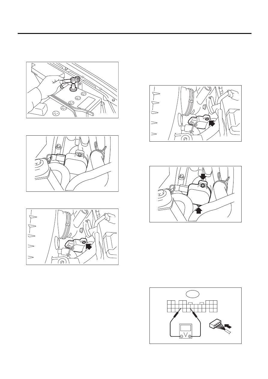
1) Disconnect battery ground cable.
2) Disconnect connector from throttle position sen-
sor.
3) Remove throttle position sensor holding screws,
and remove it.
B: INSTALLATION
Install in the reverse order of removal.
Tightening torque:
1.6 N·m (0.16 kgf-m, 1.2 ft-lb)
CAUTION:
When installing throttle position sensor, adjust
to the specified data.
C: ADJUSTMENT
1) Turn ignition switch to OFF.
2) Loosen throttle position sensor holding screws.
3) When using voltage meter;
(1) Take out ECM.
(2) Turn ignition switch to ON.
(3) Adjust throttle position sensor to the proper
position to allow the voltage signal to ECM to be
in specification.
Connector & terminal / Specified voltage
(B136) No. 15 — (B136) No. 17 / 0.45 — 0.55
V
[Fully closed.]
FU-00009
FU-00739
FU-00740
FU-00740
FU-00741
FU-00742
7 6
5 4
3 2 1
9 8
B136
20 19
17
18
16 15 14 13 12 11
30 29 28
27 26
25 24 23
22 21
10
FU(H4SOw/oOBD)-31
FUEL INJECTION (FUEL SYSTEMS)
THROTTLE POSITION SENSOR
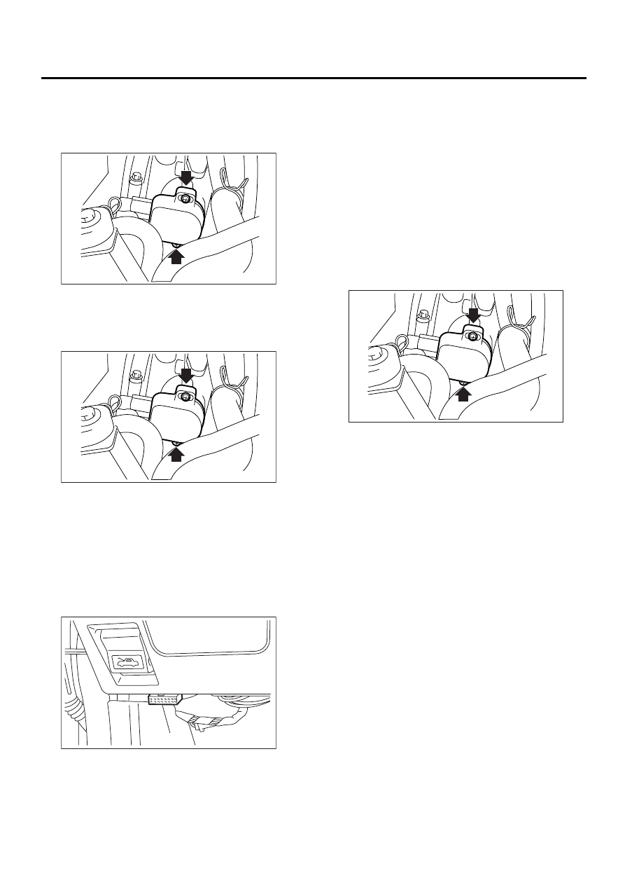
(4) Tighten throttle position sensor holding
screws.
Tightening torque:
1.6 N·m (0.16 kgf-m, 1.2 ft-lb)
4) When using Subaru Select Monitor;
(1) Turn ignition switch to OFF.
(2) Loosen throttle position sensor holding
screws.
NOTE:
For detailed operation procedures, refer to the
Subaru Select Monitor Operation Manual.
(3) Insert the cartridge to Subaru Select Moni-
tor.
<Ref. to FU(H4SOw/oOBD)-12, PREPARA-
TION TOOL, General Description.>
(4) Connect Subaru Select Monitor to the data
link connector (A).
5) Turn ignition switch to ON, and Subaru Select
Monitor switch to ON.
6) Select {2. Each System Check} in Main Menu.
7) Select {Engine Control System} in Selection
Menu.
8) Select {1. Current Data Display & Save} in En-
gine Control System Diagnosis.
9) Select {1.12 Data Display} in Data Display
Menu.
10) Adjust throttle position sensor to the proper po-
sition to match with the following specifications.
Condition: Throttle fully closed
Throttle opening angle 0.00%
Throttle sensor voltage 0.50 V
11) Tighten throttle position sensor holding screws.
Tightening torque:
1.6 N·m (0.16 kgf-m, 1.2 ft-lb)
FU-00741
FU-00741
FU-00435
( A )
FU-00741
FU(H4SOw/oOBD)-32
FUEL INJECTION (FUEL SYSTEMS)
INTAKE AIR TEMPERATURE AND PRESSURE SENSOR
9. Intake Air Temperature and
Pressure Sensor
A: REMOVAL
NOTE:
This sensor is installed on AT vehicles only.
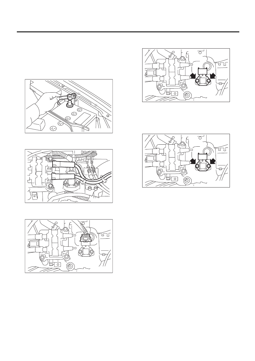
1) Disconnect battery ground cable.
2) Disconnect spark plug cord from ignition coil and
ignitor assembly.
3) Disconnect connector from intake air tempera-
ture and pressure sensor.
4) Remove intake air temperature and pressure
sensor.
B: INSTALLATION
Install in the reverse order of removal.
Tightening torque:
3.4 N·m (0.35 kgf-m, 2.5 ft-lb)
NOTE:
Replace O-ring with new one.
FU-00009
FU-00743
FU-00744
FU-00745
FU-00745
FU(H4SOw/oOBD)-33
FUEL INJECTION (FUEL SYSTEMS)
IDLE AIR CONTROL SOLENOID VALVE
10.Idle Air Control Solenoid
Valve
A: REMOVAL
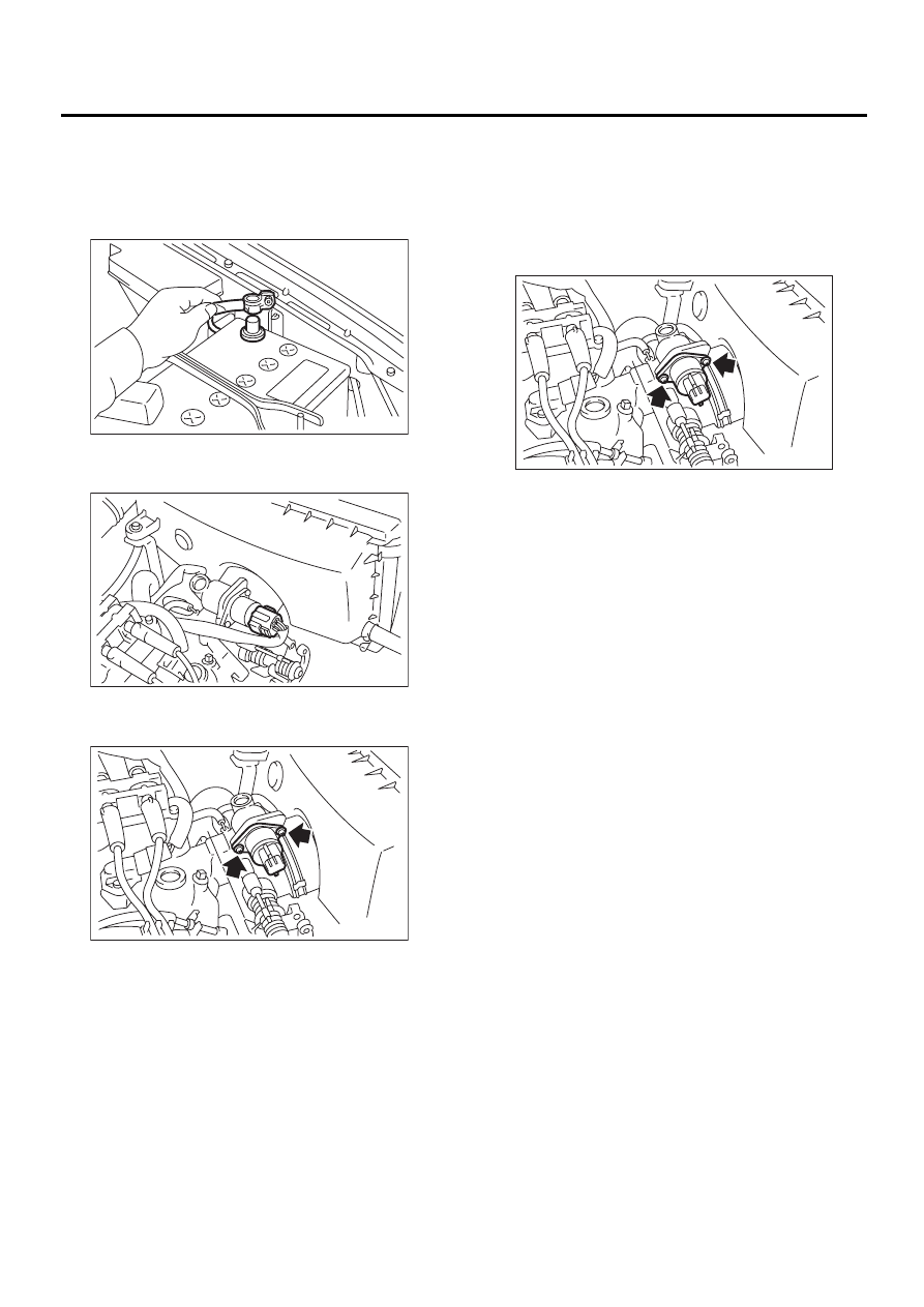
1) Disconnect battery ground cable.
2) Disconnect connector from idle air control sole-
noid valve.
3) Remove idle air control solenoid valve from
throttle body.
B: INSTALLATION
Install in the reverse order of removal.
NOTE:
Always use new gasket.
Tightening torque:
1.6 N·m (0.16 kgf-m, 1.2 ft-lb)
FU-00009
FU-00746
FU-00747
FU-00747
Нет комментариевНе стесняйтесь поделиться с нами вашим ценным мнением.
Текст