Subaru Legacy III (2000-2003 year). Service manual — part 179
FU(H4SOw/oOBD)-22
FUEL INJECTION (FUEL SYSTEMS)
INTAKE MANIFOLD
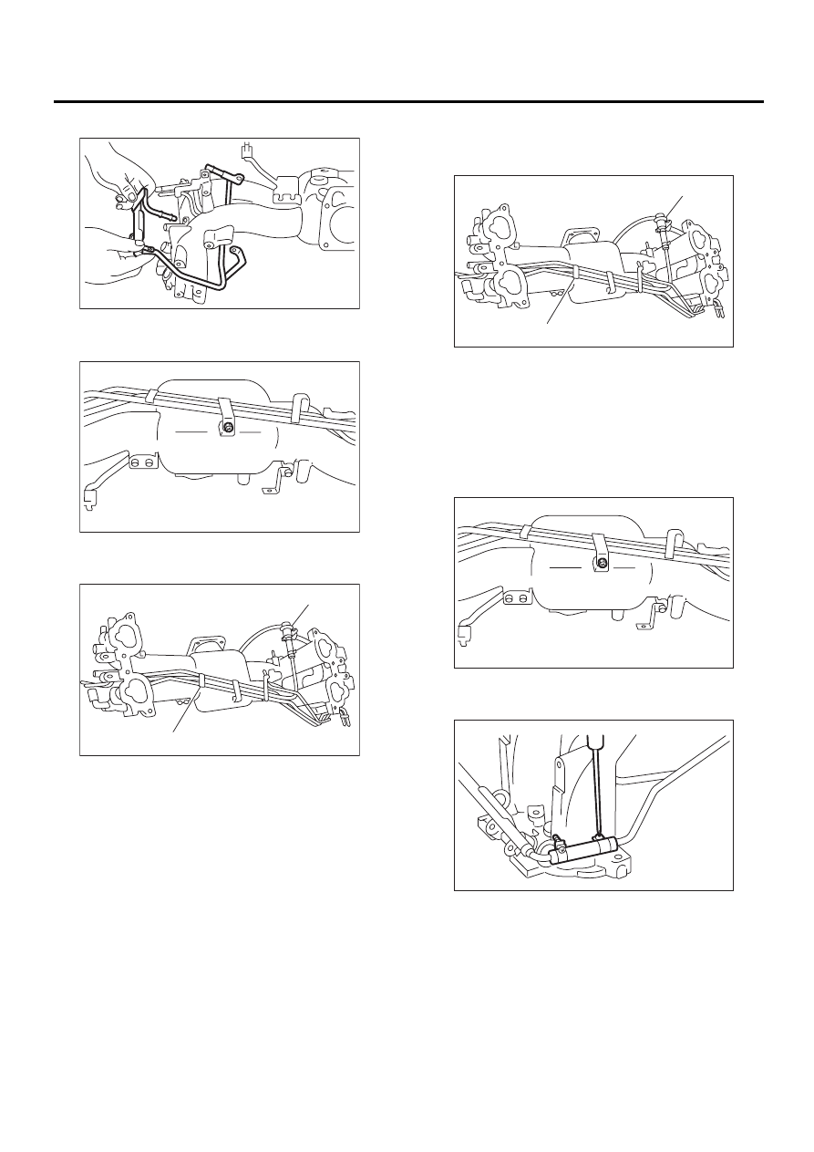
23) Remove fuel injector pipe.
24) Remove bolt which installs fuel pipes on intake
manifold.
25) Remove fuel pipe assembly and pressure reg-
ulator, from intake manifold.
D: ASSEMBLY
1) Install fuel pipe assembly and pressure regula-
tor, etc. to intake manifold.
2) Tighten bolt which installs fuel pipes on intake
manifold.
Tightening torque:
5.0 N·m (0.51 kgf-m, 3.7 ft-lb)
3) Connect right side fuel hose to injector pipe, and
tighten clamp screw.
(A) Pressure regulator
(B) Fuel pipe ASSY
FU-00735
FU-00736
FU-00737
( A )
( B )
(A) Pressure regulator
(B) Fuel pipe ASSY
FU-00737
( A )
( B )
FU-00736
FU-00279
FU(H4SOw/oOBD)-23
FUEL INJECTION (FUEL SYSTEMS)
INTAKE MANIFOLD
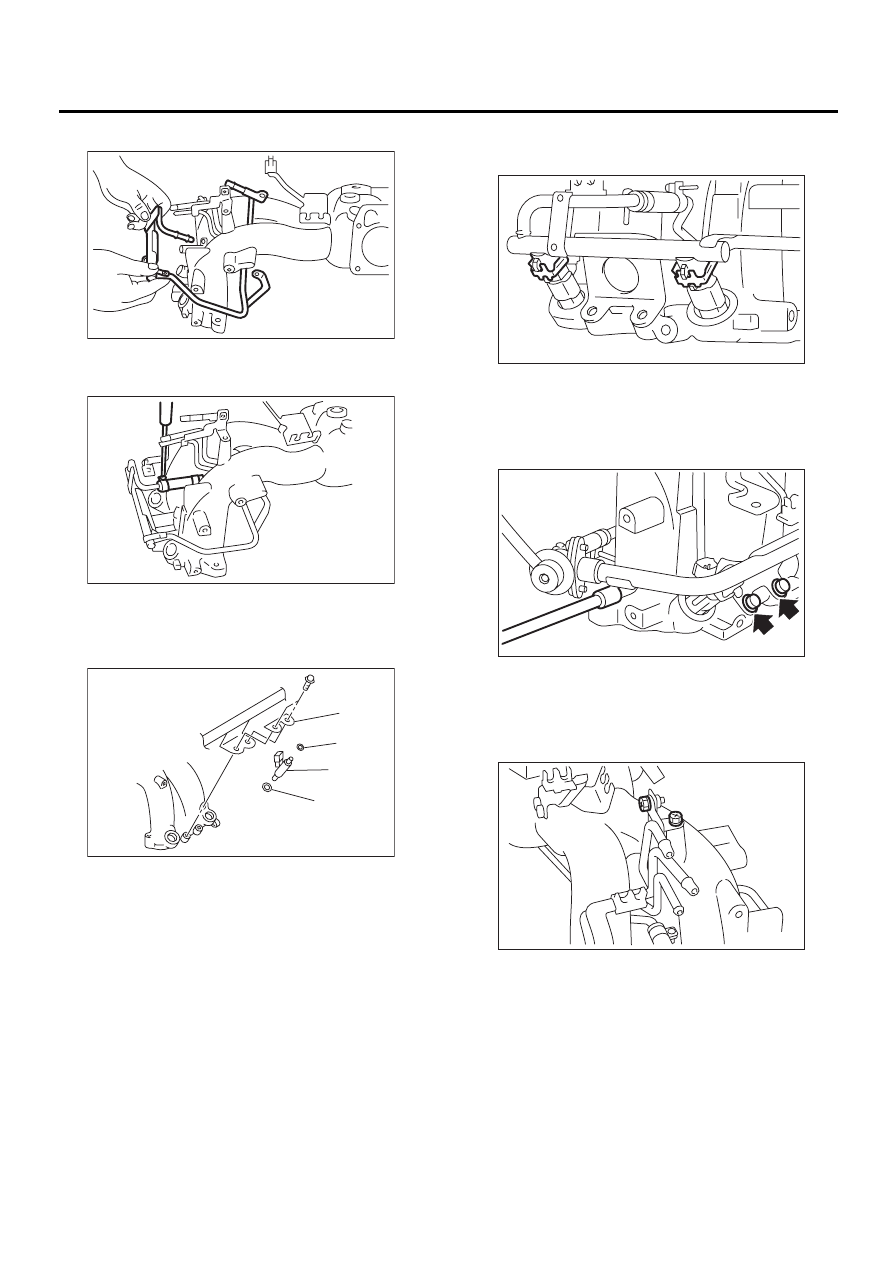
4) Install fuel injector pipe.
5) Connect left side fuel hose to injector pipe, and
tighten clamp screw.
6) Install fuel injectors.
NOTE:
Always use new O-rings and insulators.
NOTE:
Do not forget to install the fuel injector securing clip.
7) Tighten bolt which installs injector pipe on intake
manifold.
Tightening torque:
5.0 N·m (0.51 kgf-m, 3.7 ft-lb)
8) Tighten two bolts which install fuel pipes on the
left side of intake manifold.
Tightening torque:
5.0 N·m (0.51 kgf-m, 3.7 ft-lb)
(A) O-ring
(B) Fuel injector
(C) Intake manifold protector
FU-00735
FU-00734
FU-00738
( A )
( A )
( B )
( C )
FU-00733
FU-00272
FU-00732
FU(H4SOw/oOBD)-24
FUEL INJECTION (FUEL SYSTEMS)
INTAKE MANIFOLD
9) Tighten bolt which install injector pipe on intake
manifold.
Tightening torque:
5.0 N·m (0.51 kgf-m, 3.7 ft-lb)
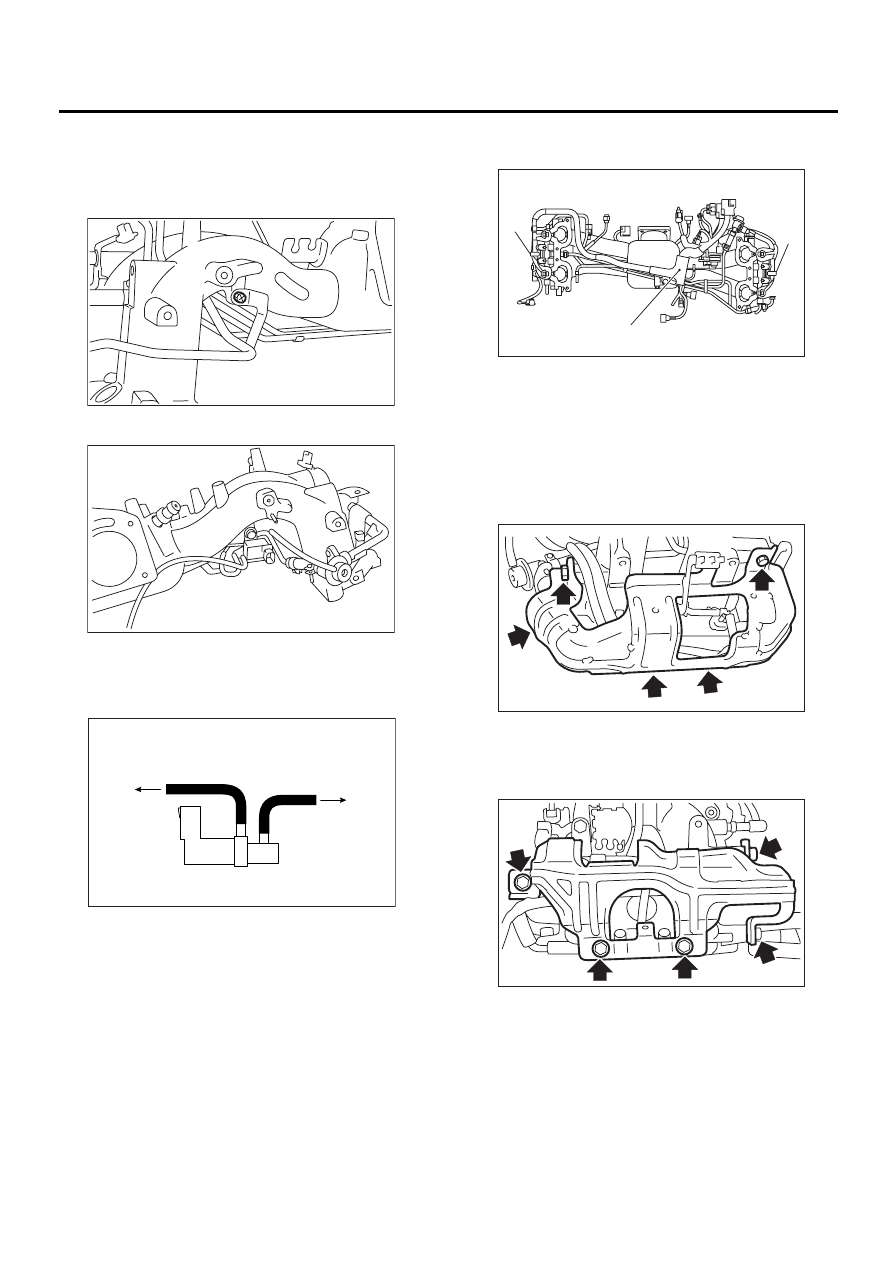
10) Install purge control solenoid valve.
11) Connect hoses to purge control solenoid valve.
NOTE:
Connect evaporation hoses as shown in the figure.
12) Install engine harness onto intake manifold.
Tightening torque:
16 N·m (1.6 kgf-m, 12 ft-lb)
13) Connect connectors to fuel injectors and purge
control solenoid valve.
14) Hold engine harness by harness band (A) and
harness bracket (B).
NOTE:
Do not use harness band on harnesses where they
are supposed to be protected by the fuel pipe pro-
tector.
15) Install intake manifold protector RH.
Tightening torque:
19 N·m (1.9 kgf-m, 13.7 ft-lb)
16) Install intake manifold protector LH.
Tightening torque:
19 N·m (1.9 kgf-m, 13.7 ft-lb)
(A) To fuel pipe
(B) To intake manifold
FU-00731
FU-00730
FU-00285
A
B
FU-00795
( A )
( A )
( B )
FU-00726
FU-00266
FU(H4SOw/oOBD)-25
FUEL INJECTION (FUEL SYSTEMS)
INTAKE MANIFOLD
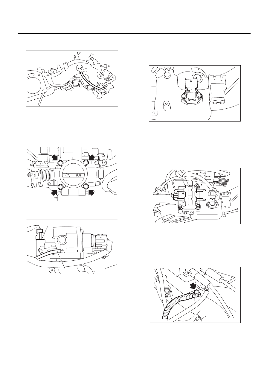
17) Connect pressure regulator vacuum hose to in-
take manifold.
18) Install throttle body to intake manifold.
NOTE:
Replace gasket with a new one.
Tightening torque:
22 N·m (2.2 kgf-m, 15.9 ft-lb)
19) Connect air by-pass hose from purge control
solenoid valve to intake manifold.
20) Install intake air temperature and pressure sen-
sor.
Tightening torque:
3.4 N·m (0.35 kgf-m, 2.5 ft-lb)
NOTE:
Replace O-ring with new one.
21) Connect connector to intake air temperature
and pressure sensor.
22) Connect connectors to throttle position sensor
and idle air control solenoid valve.
23) Install ignition coil and ignitor assembly.
24) Connect connector to ignition coil and ignitor
assembly.
25) Install engine ground terminal to intake mani-
fold.
Tightening torque:
19 N·m (1.9 kgf-m, 13.7 ft-lb)
E: INSPECTION
Make sure the fuel pipe and fuel hoses are not
cracked and that connections are tight.
(A) Throttle position sensor
(B) Idle air control soleoid valve
(C) Air by-pass hose
FU-00265
FU-00725
FU-00716
( B )
( A )
( C )
FU-00724
FU-00722
FU-00263
Нет комментариевНе стесняйтесь поделиться с нами вашим ценным мнением.
Текст