Subaru Legacy III (2000-2003 year). Service manual — part 557
AT-122
AUTOMATIC TRANSMISSION
DRIVE PINION SHAFT
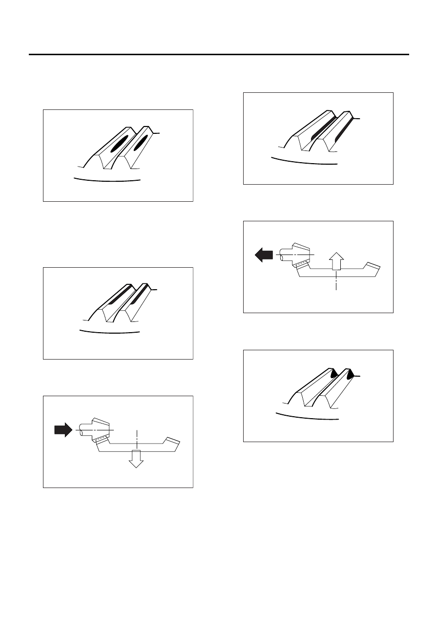
• Tooth contact
Checking item:Tooth contact pattern is slightly
shifted toward to toe side under no-load
rotation. [When loaded, contact pattern moves
toward heel.]
• Face contact
Checking item: Backlash is too large.
Contact pattern
Corrective action: Increase thickness of drive pin-
ion height adjusting shim in order to bring drive pin-
ion close to crown gear.
• Flank contact
Checking item: Backlash is too small.
Contact pattern
Corrective action: Reduce thickness of drive pinion
height adjusting shim in order to move drive pinion
away from crown gear.
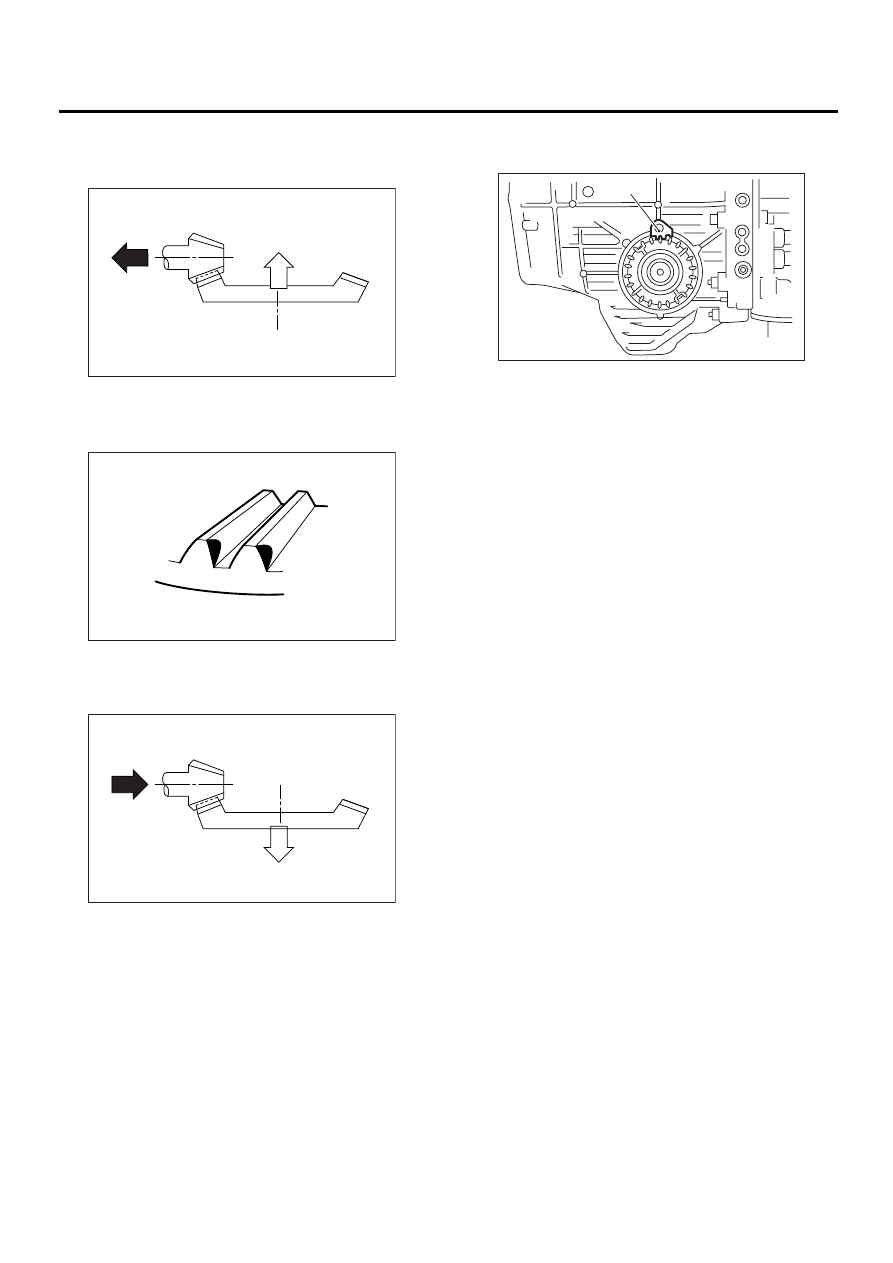
• Toe contact (Inside end contact)
Checking item: Contact areas is small.
Contact pattern
(A) Toe side
(B) Heel side
AT-00207
(A)
(B)
AT-00208
AT-00212
AT-00209
AT-00213
AT-00210
AT-123
AUTOMATIC TRANSMISSION
DRIVE PINION SHAFT
Corrective action: Decrease thickness of drive pin-
ion height adjusting shim in order to move drive pin-
ion away from crown gear.
• Heel contact (Outside end contact)
Checking item: Contact areas is small.
Contact pattern
Corrective action: Increase thickness of drive pin-
ion height adjusting shim in order to move drive pin-
ion close to crown gear.
6) If tooth contact is correct, mark the retainer posi-
tion and loosen it. After fitting a new O-ring and oil
seal, screw in the retainer to the marked position.
Then tighten the lock plate to the specified torque.
Tightening torque:
25 N·m (2.5 kgf-m, 18.1 ft-lb)
AT-00213
AT-00211
AT-00212
(A) Lock plate
AT-00214
( A )
AT-124
AUTOMATIC TRANSMISSION
FRONT DIFFERENTIAL
36.Front Differential
A: REMOVAL
1) Remove the transmission assembly from the ve-
hicle. <Ref. to AT-39, REMOVAL, Automatic
Transmission Assembly.>
2) Extract the torque converter clutch assembly.
<Ref. to AT-85, REMOVAL, Torque Converter
Clutch Assembly.>
3) Remove the input shaft.
4) Disconnect the air breather hose. <Ref. to AT-
83, REMOVAL, Air Breather Hose.>
5) Lift-up lever behind the transmission harness
connector and disconnect it from stay.
6) Disconnect inhibitor switch from stay.
7) Remove the oil charger pipe. <Ref. to AT-84,
REMOVAL, Oil Charger Pipe.>
8) Remove the oil cooler inlet and outlet pipes.
<Ref. to AT-78, REMOVAL, ATF Cooler Pipe and
Hose.>
9) Separation of torque converter clutch case and
transmission case.<Ref. to AT-109, REMOVAL,
Torque Converter Clutch Case.>
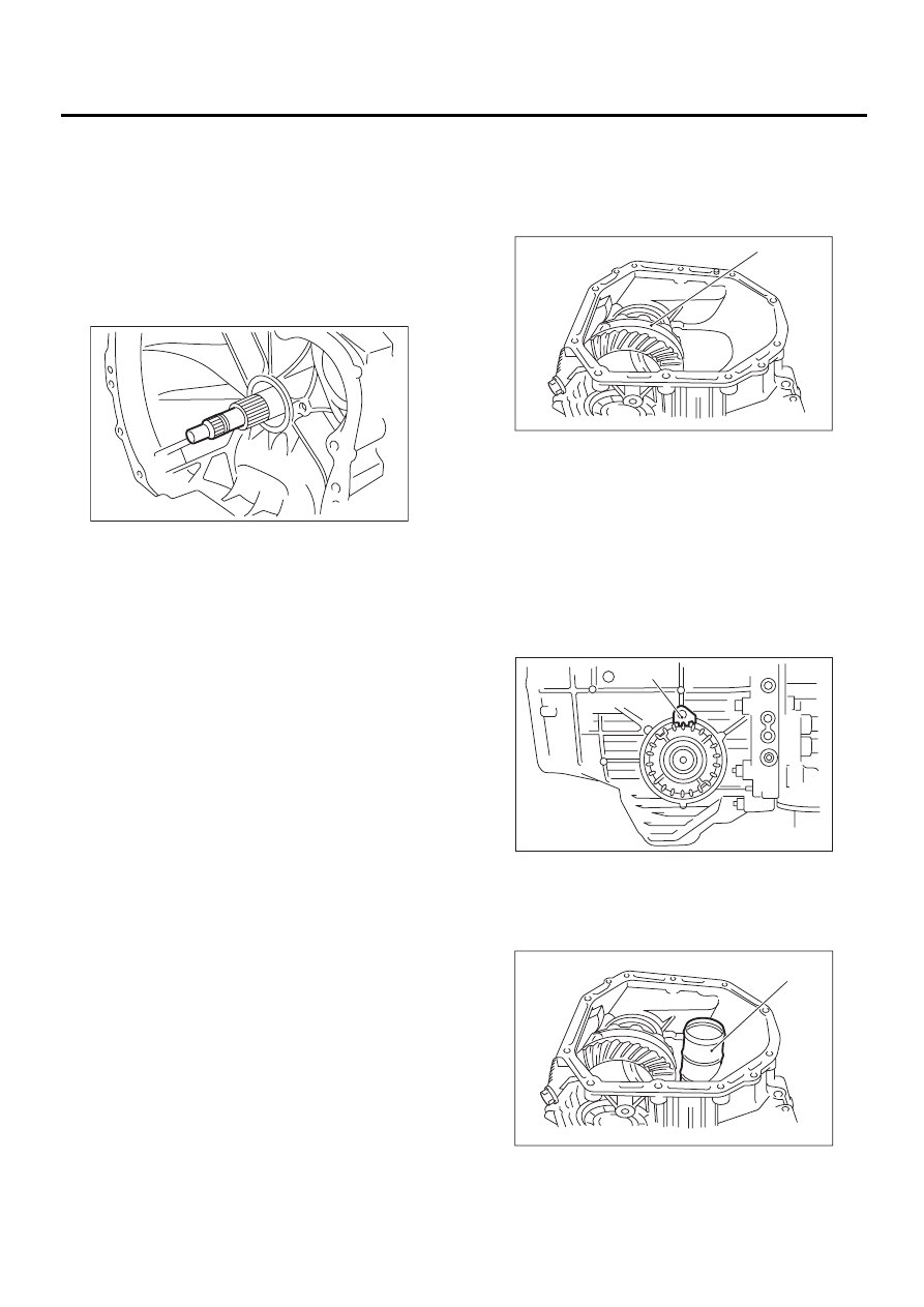
10) Remove the seal pipe if it is attached.
11) Remove the differential side retainer with ST.
NOTE:
Hold the differential case assembly by hand to
avoid damaging retainer mounting hole of the
torque converter clutch case.
ST
499787000
WRENCH ASSY
12) Remove the differential assembly without dam-
aging installation part of retainer.
B: INSTALLATION
1) Install the differential assembly to the case, pay-
ing special attention not to damage the inside of the
case (particularly, the differential side retainer con-
tact surface).
2) Remove the O-rings from left and right side re-
tainer.
3) Using ST, install the side retainers. <Ref. to AT-
124, REMOVAL, Front Differential.>
ST
499787000
WRENCH ASSY
4) Install the lock plate.
Tightening torque:
25 N·m (2.5 kgf-m, 18.1 ft-lb)
5) Install the new seal pipe to the torque converter
clutch case.
AT-00114
(A) Differential assembly
(A) Lock plate
(A) Seal pipe
AT-00215
( A )
AT-00214
( A )
AT-00176
( A )

AT-125
AUTOMATIC TRANSMISSION
FRONT DIFFERENTIAL
6) Install the torque converter clutch case to trans-
mission case. <Ref. to AT-110, INSTALLATION,
Torque Converter Clutch Case.>
7) Install air breather hose.
8) Insert inhibitor switch and transmission connec-
tor into stay.
9) Install oil cooler pipes. <Ref. to AT-80, INSTAL-
LATION, ATF Cooler Pipe and Hose.>
10) Install the oil charger pipe with O-ring <Ref. to
AT-84, INSTALLATION, Oil Charger Pipe.>
11) Insert the input shaft while turning lightly by
hand. At this time, not to damage the bushing.
Normal protrusion A:
50 — 55 mm (1.97 — 2.17 in)
12) Install the torque converter clutch assembly.
<Ref. to AT-85, INSTALLATION, Torque Converter
Clutch Assembly.>
13) Install the transmission assembly to the vehi-
cle. <Ref. to AT-42, INSTALLATION, Automatic
Transmission Assembly.>
C: DISASSEMBLY
1. DIFFERENTIAL CASE ASSEMBLY
1) Using a press and ST, remove the taper roller
bearing.
ST
498077000
REMOVER
2) Secure the case in a vise and remove the crown
gear tightening bolts, then separate the crown
gear, case (RH) and case (LH).
3) Pull out the straight pin and shaft, and remove
the differential bevel gear, washer, and differential
bevel pinion.
(A) Transmission harness
(B) Inhibitor switch harness
AT-00174
( B )
( A )
AT-00291
A
(A) Crown gear
(B) Differential case (RH)
(C) Differential case (LH)
(A) Differential case (RH)
AT-00216
ST
AT-00217
( A )
( B )
( C )
AT-00218
( A )
Нет комментариевНе стесняйтесь поделиться с нами вашим ценным мнением.
Текст