Subaru Legacy III (2000-2003 year). Service manual — part 556
AT-118
AUTOMATIC TRANSMISSION
DRIVE PINION SHAFT
35.Drive Pinion Shaft
A: REMOVAL
1) Remove the transmission assembly from vehi-
cle. <Ref. to AT-39, REMOVAL, Automatic Trans-
mission Assembly.>
2) Extract the torque converter clutch assembly.
<Ref. to AT-85, REMOVAL, Torque Converter
Clutch Assembly.>
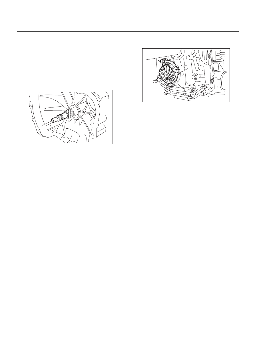
3) Remove the input shaft.
4) Lift-up lever behind the transmission harness
connector and disconnect it from stay.
5) Disconnect inhibitor switch connector from stay.
6) Disconnect the air breather hose. <Ref. to AT-
83, REMOVAL, Air Breather Hose.>
7) Remove the oil charger pipe. <Ref. to AT-84,
REMOVAL, Oil Charger Pipe.>
8) Remove the oil cooler inlet and outlet pipes.
<Ref. to AT-78, REMOVAL, ATF Cooler Pipe and
Hose.>
9) Separation of torque converter clutch case and
transmission case sections <Ref. to AT-109, RE-
MOVAL, Torque Converter Clutch Case.>
10) Separate transmission case and extension
case sections. <Ref. to AT-86, REMOVAL, Exten-
sion Case.>
11) Remove the reduction drive gear. (MPT model)
<Ref. to AT-104, REMOVAL, Reduction Drive
Gear.>
12) Remove the center differential carrier. (VTD
model) <Ref. to AT-106, REMOVAL, Center Differ-
ential Carrier.>
13) Remove the reduction driven gear.
<Ref. to AT-101, REMOVAL, Reduction Driven
Gear.>
14) Separation of drive pinion shaft and oil pump
housing. <Ref. to AT-112, REMOVAL, Oil Pump.>
AT-00114
AT-00180
AT-119
AUTOMATIC TRANSMISSION
DRIVE PINION SHAFT
B: INSTALLATION
1) Assemble the drive pinion assembly to the oil
pump housing. <Ref. to AT-113, INSTALLATION,
Oil Pump.>
2) Install oil pump housing to transmission case.
<Ref. to AT-113, INSTALLATION, Oil Pump.>
3) Combine the torque converter case with the
transmission case. <Ref. to AT-110, INSTALLA-
TION, Torque Converter Clutch Case.>
4) Install the reduction driven gear.
<Ref. to AT-102, INSTALLATION, Reduction Driv-
en Gear.>
5) Install the reduction drive gear. (MPT model)
<Ref. to AT-104, INSTALLATION, Reduction Drive
Gear.>
6) Install the center differential carrier. (VTD model)
<Ref. to AT-106, INSTALLATION, Center Differen-
tial Carrier.>
7) Combine the extension case with the transmis-
sion case, and install vehicle speed sensor 1 (rear).
<Ref. to AT-86, INSTALLATION, Extension Case.>
8) Insert inhibitor switch and transmission connec-
tor into stay.
9) Install air breather hose. <Ref. to AT-83, IN-
STALLATION, Air Breather Hose.>
10) Install the oil cooler inlet and outlet pipes. <Ref.
to AT-80, INSTALLATION, ATF Cooler Pipe and
Hose.>
11) Install the oil charger pipe with O-ring.
12) Insert the input shaft while turning lightly by
hand. At this time, not to damage the bushing.
Normal protrusion A:
50 — 55 mm (1.97 — 2.17 in)
13) Install the torque converter clutch assembly.
<Ref. to AT-85, INSTALLATION, Torque Converter
Clutch Assembly.>
14) Install the transmission assembly to vehicle.
<Ref. to AT-42, INSTALLATION, Automatic Trans-
mission Assembly.>
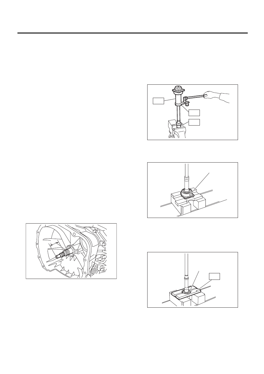
C: DISASSEMBLY
1) Straighten the staked portion of the lock nut, and
remove the lock nut while locking the rear spline
portion of the shaft with ST1 and ST2. Then pull off
the drive pinion collar.
ST1
498937110
HOLDER
ST2
499787700
WRENCH
ST3
499787500
ADAPTER
2) Remove the O-ring.
3) Using a press, separate the rear roller bearing
and outer race from the shaft.
4) Using a press and ST, separate the front roller
bearing from the shaft.
ST
498517000
REPLACER
AT-00291
A
(A) Outer race
(A) Front roller bearing
AT-00197
ST1
ST2
ST3
AT-00198
( A )
AT-00199
( A )
ST
AT-120
AUTOMATIC TRANSMISSION
DRIVE PINION SHAFT
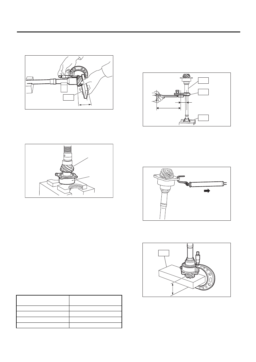
D: ASSEMBLY
1) Measure dimension “A” of the drive pinion shaft.
ST
398643600
GAUGE
2) Using a press, force-fit a new roller bearing in
position.
NOTE:
If too much pressure is applied, the roller bearing
will not turn easily.
3) After fitting a new O-ring to the shaft, attach the
drive pinion collar to the shaft.
4) Install the lock washer to drive pinion shaft in
proper direction.
5) Tighten a new lock nut with ST1, ST2 and ST3.
Calculate lock washer and lock nut specifications
using the following formula.
T2 = L2/(L1 + L2)
×
T1
T1:
116 N·m (11.8 kgf-m, 85.3 ft-lb)
[Required torque setting]
T2:
Tightening torque
L1:
ST2 length 0.072 m (2.83 in)
L2:
Torque wrench length
Example:
ST1
498937110
HOLDER
ST2
499787700
WRENCH
ST3
499787500
ADAPTER
NOTE:
Install ST2 to torque wrench as straight as possi-
ble.
6) Measure the starting torque of the bearing. Make
sure the starting torque is within the specified
range. If out of the allowable range, replace the roll-
er bearing.
Starting torque:
7.6 — 38.1 N (0.776 — 3.88 kgf, 1.7 — 8.6 lb)
7) Stake the lock nut securely at two places.
8) Measure dimension “B” of the drive pinion shaft.
ST
398643600
GAUGE
9) The thickness “t” (mm) of the drive pinion shim.
t = 6.5
±±±±
0.0625
−−−−
(B
−−−−
A)
10) Select three or less shims from following table.
(A) Drive pinion shaft
(B) Roller bearing
Torque wrench length
m (in)
Tightening torque
N·m (kgf-m, ft-lb)
0.4 (15.75)
98 (10.0, 72)
0.45 (17.72)
100 (10.2, 73.8)
0.5 (19.69)
101 (10.3, 74.5)
0.55 (21.65)
102 (10.4, 75)
AT-00200
A
ST
AT-00201
( A )
( B )
L2 [m (in)]
L1 [m (in)]
AT-00202
ST1
ST2
ST3
AT-00203
AT-00204
B
ST
AT-121
AUTOMATIC TRANSMISSION
DRIVE PINION SHAFT
E: INSPECTION
• Make sure that all component parts are free of
harmful cuts, gouges, and other faults.
• Adjust the teeth alignment. <Ref. to AT-121, AD-
JUSTMENT, Drive Pinion Shaft.>
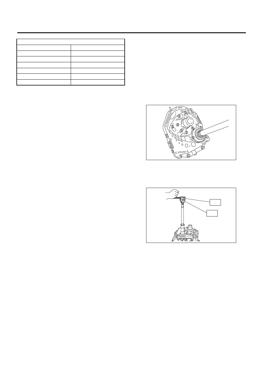
F: ADJUSTMENT
1) Thoroughly remove the liquid gasket from the
case mating surface beforehand.
2) Install the oil pump housing assembly to the
torque converter clutch case, and secure evenly by
tightening four bolts.
NOTE:
Use an old gasket or an aluminum washer so as not
to damage the mating surface of the housing.
Tightening torque:
41 N·m (4.2 kgf-m, 30.4 ft-lb)
3) Rotate the drive pinion several times with ST1
and ST2.
ST1
498937110
HOLDER
ST2
499787700
WRENCH
4) Adjust the backlash between drive pinion and
crown gear. <Ref. to AT-128, ADJUSTMENT,
Front Differential.>
5) Apply red lead evenly to the surfaces of three or
four teeth of the crown gear. Rotate the drive pinion
in the forward and reverse directions several times.
Then remove the oil pump housing, and check the
tooth contact pattern.
If tooth contact is improper, readjust the backlash
or shim thickness.<Ref. to AT-128, ADJUSTMENT,
Front Differential.>
Available drive pinion shims
Part No.
Thickness mm (in)
31451AA050
0.150 (0.0059)
31451AA060
0.175 (0.0069)
31451AA070
0.200 (0.0079)
31451AA080
0.225 (0.0089)
31451AA090
0.250 (0.0098)
31451AA100
0.275 (0.0108)
AT-00205
AT-00206
ST1
ST2
Нет комментариевНе стесняйтесь поделиться с нами вашим ценным мнением.
Текст