Subaru Legacy III (2000-2003 year). Service manual — part 558
AT-126
AUTOMATIC TRANSMISSION
FRONT DIFFERENTIAL
2. SIDE RETAINER
NOTE:
After adjusting the drive pinion backlash and tooth
contact, remove and install the oil seal and O-ring.
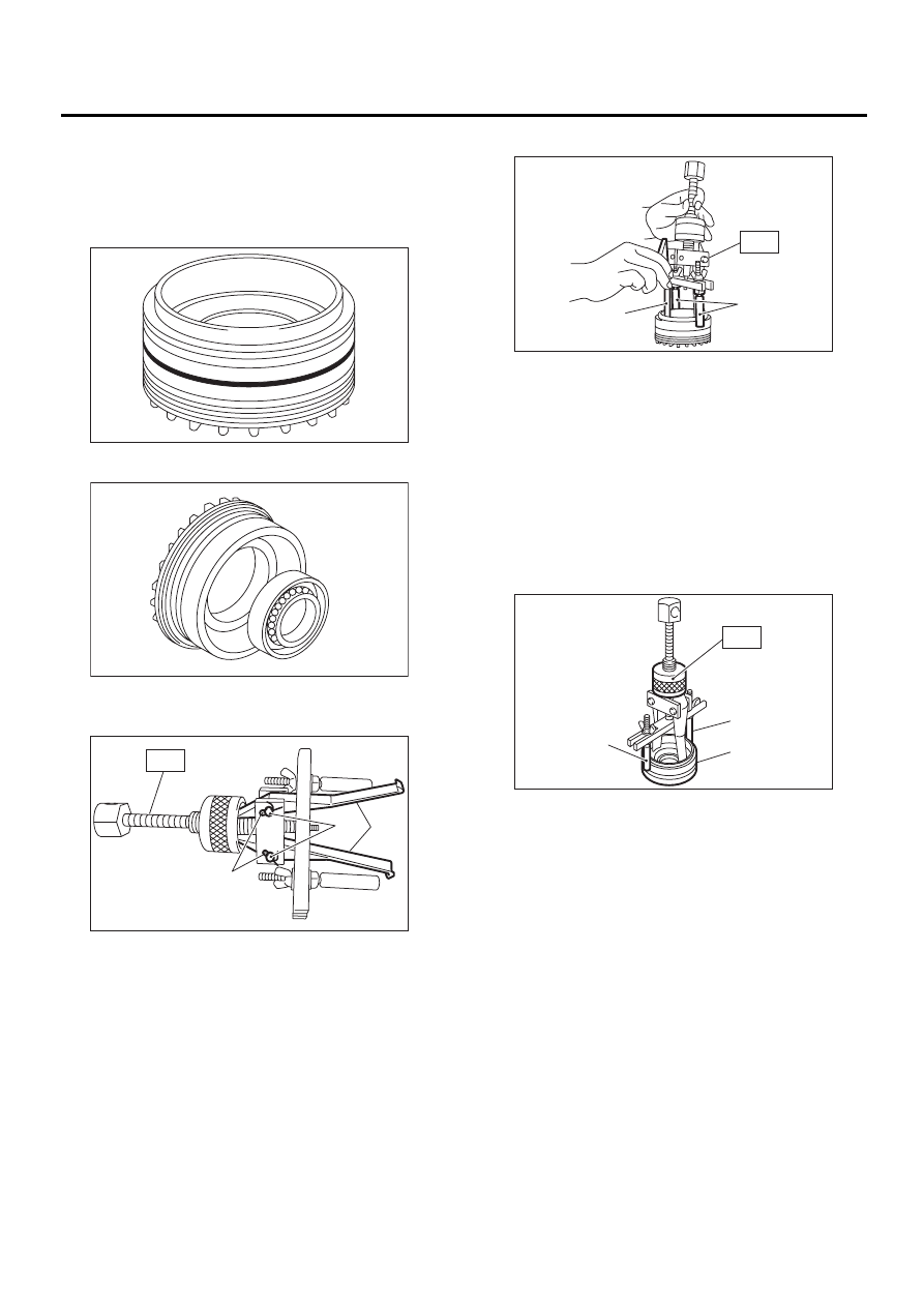
1) Remove O-ring.
2) Remove oil seal.
3) Take out either split pin, remove claw.
ST
398527700
PULLER ASSY
4) Securely attach two claws to outer race, set ST
to side retainer.
ST
398527700
PULLER ASSY
5) Return removed claw to the original position,
and install pin and split pin.
6) Hold the shaft of ST to avoid removing from side
retainer, and then remove the bearing outer race.
ST
398527700
PULLER ASSY
NOTE:
Replace bearing inner and outer races as a single
unit.
(A) Claw
(B) Split pin
(C) Pin
AT-00219
AT-00220
AT-00221
ST
( A )
( B )
( C )
(A) Shaft
(B) Claw
(A) Shaft
(B) Side retainer
AT-00222
( A )
( B )
ST
AT-00223
ST
( B )
( A )
AT-127
AUTOMATIC TRANSMISSION
FRONT DIFFERENTIAL
D: ASSEMBLY
1. DIFFERENTIAL CASE ASSEMBLY
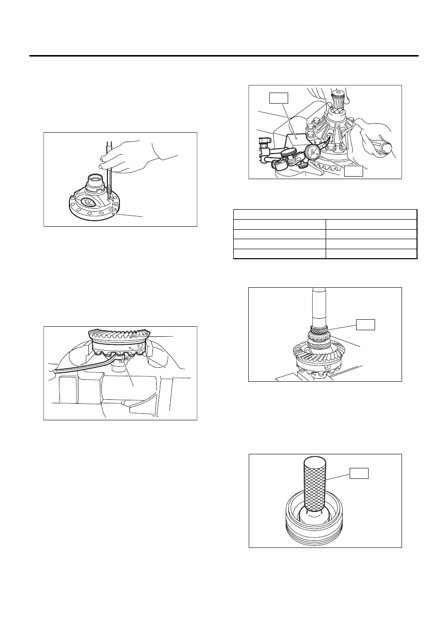
1) Install the washer, differential bevel gear and dif-
ferential bevel pinion in the differential case (RH).
Insert the pinion shaft.
2) Install straight pin from reverse direction.
3) Install the washer and differential bevel gear to
the differential case (LH). Then put the case over
the differential case (RH), and connect both cases.
4) Install the crown gear and secure by tightening
the bolt.
Standard tightening torque:
62 N·m (6.3 kgf-m, 45.6 ft-lb)
5) Measurement of backlash (Selection of washer)
(1) Measure the gear backlash with ST1 and
ST2, and insert ST2 through the access window
of the case.
ST1
498247001
MAGNET BASE
ST2
498247100
DIAL GAUGE
NOTE:
• Measure the backlash by applying a pinion tooth
between two bevel gear teeth.
• Fix bevel pinion gear in place with a screwdriver
or similar tool when measuring.
Standard value:
0.13 — 0.18 mm (0.0051 — 0.0071 in)
(2) If backlash is not as specified, select a
washer from the table below.
6) Using ST, install taper roller bearing.
ST
398437700
DRIFT
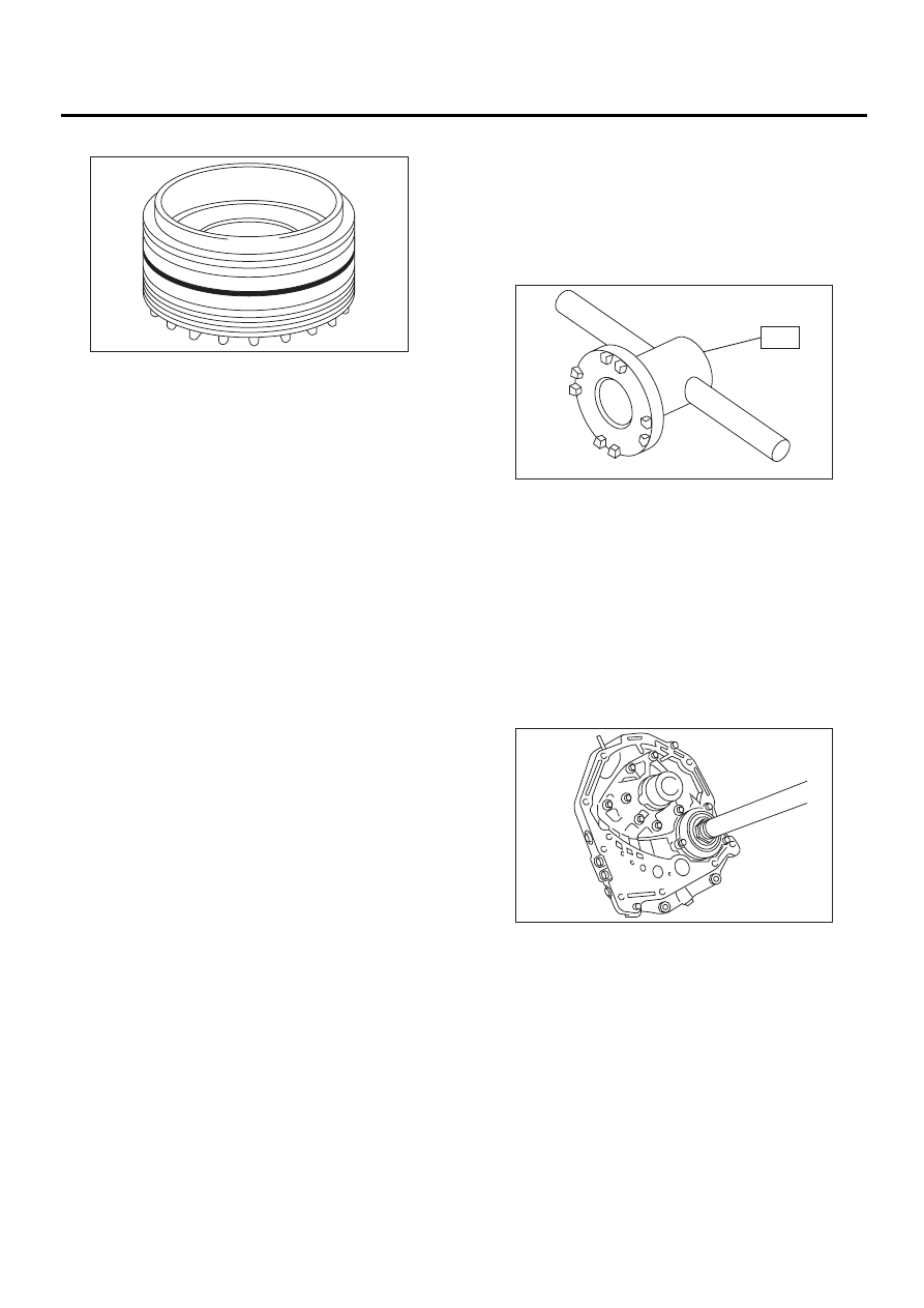
2. SIDE RETAINER
1) Install bearing outer race to side retainer.
2) Install a new oil seal using the ST and hammer.
ST
499797000
INSTALLER
(A) Differential case (RH)
(A) Crown gear
(B) Differential case (RH)
(C) Differential case (LH)
AT-00218
( A )
AT-00217
( A )
( B )
( C )
Washer
Part No.
Thickness mm (in)
803038021
0.95 (0.037)
803038022
1.00 (0.039)
803038023
1.05 (0.041)
(A) Taper roller bearing
AT-00224
ST2
ST1
AT-00225
( A )
ST
AT-00711
ST
AT-128
AUTOMATIC TRANSMISSION
FRONT DIFFERENTIAL
3) Install new O-ring.
E: INSPECTION
• Check each component for harmful cuts, dam-
age and other faults.
• Measure the backlash and adjust to within spec-
ifications.
<Ref. to AT-128, ADJUSTMENT, Front Differen-
tial.>
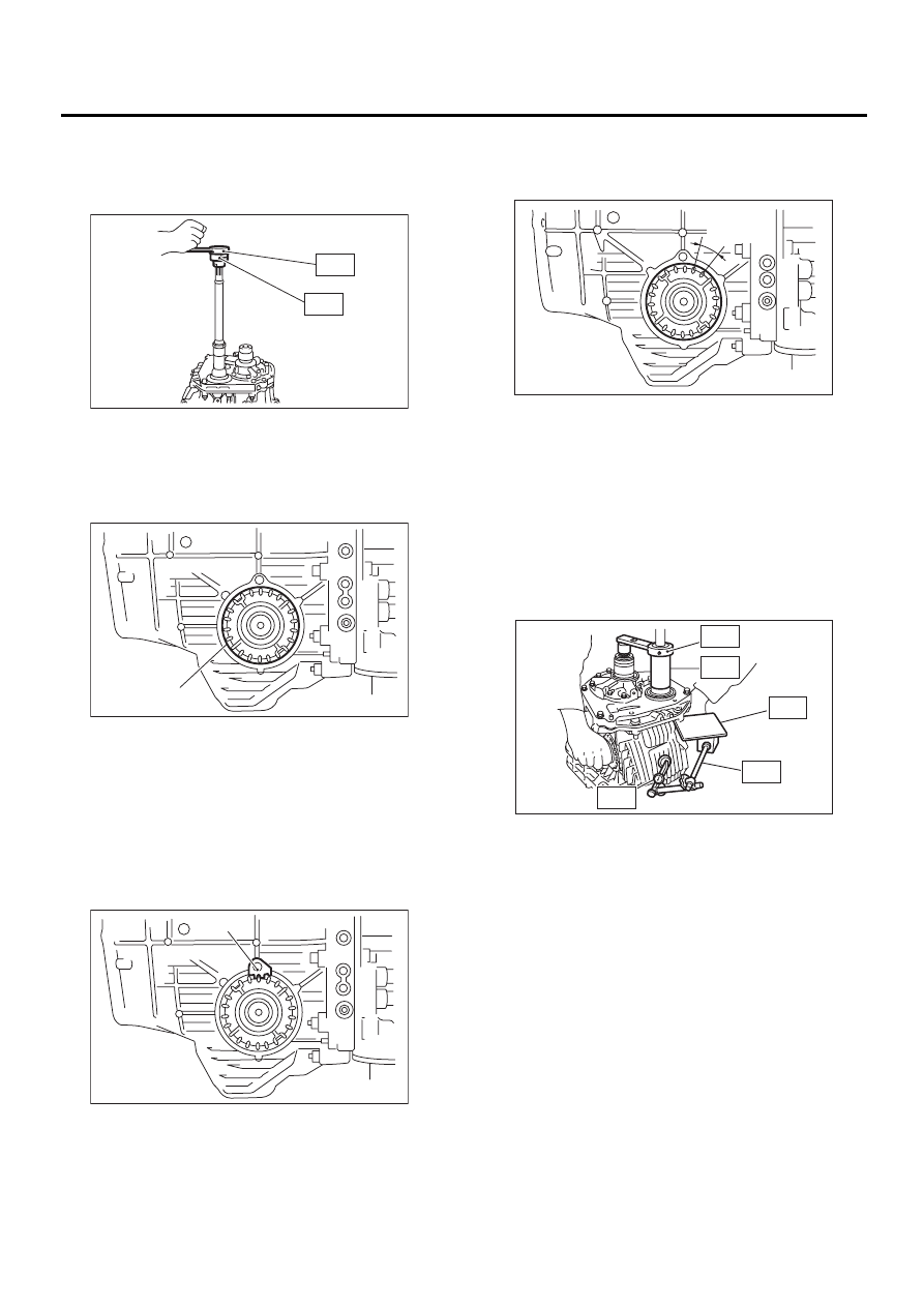
F: ADJUSTMENT
1) Using ST, screw in the retainer until light contact
is felt.
NOTE:
Screw in the RH side slightly deeper than the LH
side.
ST
499787000 WRENCH
ASSY
2) Remove the oil pump housing.
3) Thoroughly remove the liquid gasket from the
case mating surface beforehand.
4) Install the oil pump housing assembly to the
torque converter clutch case, and secure evenly by
tightening four bolts.
NOTE:
Use an old gasket or an aluminum washer so as not
to damage the mating surface of the housing.
Tightening torque:
41 N·m (4.2 kgf-m, 30.4 ft-lb)
AT-00219
AT-00227
ST
AT-00205
AT-129
AUTOMATIC TRANSMISSION
FRONT DIFFERENTIAL
5) Rotate the drive pinion several times with ST1
and ST2.
ST1
498937110
HOLDER
ST2
499787700
WRENCH
6) Tighten the LH retainer until contact is felt while
rotating the shaft. Then loosen the RH retainer.
Keep tightening the LH retainer and loosening the
RH retainer until the pinion shaft can no longer be
turned. This is the “zero” state.
7) After the “zero” state is established, back off the
LH retainer 3 notches and secure it with the lock
plate. Then back off the RH retainer and retighten
until it stops. Rotate drive pinion a few times. Tight-
en the RH retainer 1-3/4 notches further. This sets
the preload. Finally, secure the retainer with its lock
plate.
NOTE:
Turning the retainer by one tooth changes the
backlash about 0.05 mm (0.0020 in).
8) Turn the drive pinion several rotations with ST1
and check to see if the backlash is within the stan-
dard value with ST2, ST3, ST4 and ST5.
ST1
499787700
WRENCH
ST2
498247001
MAGNET BASE
ST3
498247100
DIAL GAUGE
ST4
499787500
ADAPTER
ST5
498255400
PLATE
Backlash:
0.13 — 0.18 mm (0.0051 — 0.0071 in)
9) Adjust the tooth contact between front differen-
tial and drive shaft. <Ref. to AT-121, ADJUST-
MENT, Drive Pinion Shaft.>
(A) Retainer
(A) Lock plate
AT-00206
ST1
ST2
AT-00229
( A )
AT-00214
( A )
0.05 mm
(0.0020 in)
AT-00230
AT-00231
ST1
ST4
ST5
ST2
ST3
Нет комментариевНе стесняйтесь поделиться с нами вашим ценным мнением.
Текст