Subaru Legacy III (2000-2003 year). Service manual — part 725

ABS-118
ABS (DIAGNOSTICS)
DIAGNOSTICS CHART WITH SUBARU SELECT MONITOR
W: DTC 44 ABS-AT CONTROL (NON CONTROLLED)
DIAGNOSIS:
• Combination of AT control faults
TROUBLE SYMPTOM:
• ABS does not operate.
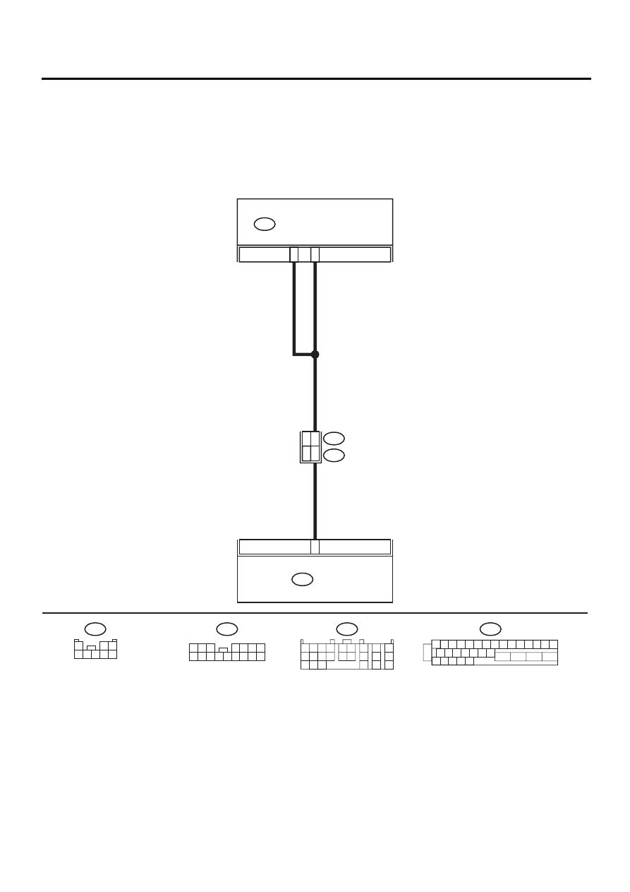
WIRING DIAGRAM:
ABS00310
1 2 3 4 5 6 7 8 9 10 11 12 13 14 15
16 17 18 19 20 21 22
27 28 29 30 31
23
24
25
26
F49
31
3
ABS CONTROL MODULE AND
HYDRAULIC CONTROL UNIT
F49
TCM
B55
21
7
14
B62
F45
RHD
LHD
:LHD
F45
:RHD
1 2 3
4 5 6 7
8 9 10 11 12 13 14 15 16
F45
1
2 3
4 5 6 7 8
B55
1 2 3 4
10 11 12
19 20 21
13
5 6
14 15
7
8
9
16
17
18
22
23
24

ABS-119
ABS (DIAGNOSTICS)
DIAGNOSTICS CHART WITH SUBARU SELECT MONITOR
Step
Value
Yes
No
1
CHECK SPECIFICATIONS OF THE AB-
SCM&H/U.
Check specifications of the mark to the
ABSCM&H/U.
CG: AT (except OUTBACK)
CH: MT (except OUTBACK)
CI: AT (OUTBACK)
CJ: MT (OUTBACK)
Do the vehicle specification and the specifica-
tion of ABSCM&HU match?
Both are the same specifica-
tions.
Replace
ABSCM&H/U.
<Ref. to ABS-6,
ABS Control Mod-
ule and Hydraulic
Control Unit
(ABSCM&H/U).>
2
CHECK GROUND SHORT OF HARNESS.
1) Turn ignition switch to OFF.
2) Disconnect two connectors from TCM.
3) Disconnect connector from ABSCM&H/U.
4) Measure resistance between ABSCM&H/U
connector and chassis ground.
Connector & terminal
(F49) No. 3 — Chassis ground:
Does the measured value exceed the spec-
ified value?
1 M
Ω
Repair harness
between TCM and
ABSCM&H/U.
3
CHECK TCM.
1) Connect all connectors to TCM.
2) Turn ignition switch to ON.
3) Measure voltage between TCM connector
terminal and chassis ground.
Connector & terminal
(B55) No. 21 (+) — Chassis ground (
−−−−
):
Is the measured value within the specified
range?
10 - 15 V
4
CHECK AT.
Is the AT functioning normally?
Function of AT is normal.
Replace TCM.
Repair AT.
5
CHECK OPEN CIRCUIT OF HARNESS.
Measure voltage between ABSCM&H/U con-
nector and chassis ground.
Connector & terminal
(F49) No. 3 (+) — Chassis ground (
−−−−
):
(F49) No. 31 (+) — Chassis ground (
−−−−
):
Is the measured value within the specified
range?
10 - 15 V
Repair harness/
connector
between TCM and
ABSCM&H/U.
6
CHECK POOR CONTACT IN CONNECTORS.
Is there poor contact in connectors between
TCM and ABSCM&H/U?
There is no poor contact.
Repair connector.
7
CHECK ABSCM&H/U.
1) Connect all connectors.
2) Erase the memory.
3) Perform inspection mode.
4) Read out the DTC.
Is the same DTC still being output?
Same DTC is not indicated.
Replace
ABSCM&H/U.
<Ref. to ABS-6,
ABS Control Mod-
ule and Hydraulic
Control Unit
(ABSCM&H/U).>
8
CHECK ANY OTHER DTC APPEARANCE.
Are other DTC being output?
Other DTC is not indicated.
A temporary poor
contact.
Proceed with the
diagnosis corre-
sponding to the
DTC.
ABS-120
ABS (DIAGNOSTICS)
DIAGNOSTICS CHART WITH SUBARU SELECT MONITOR
X: DTC 44 ABS-AT CONTROL (CONTROLLED)
DIAGNOSIS:
• Combination of AT control faults
TROUBLE SYMPTOM:
• ABS does not operate.
WIRING DIAGRAM:
ABS00310
1 2 3 4 5 6 7 8 9 10 11 12 13 14 15
16 17 18 19 20 21 22
27 28 29 30 31
23
24
25
26
F49
31
3
ABS CONTROL MODULE AND
HYDRAULIC CONTROL UNIT
F49
TCM
B55
21
7
14
B62
F45
RHD
LHD
:LHD
F45
:RHD
1 2 3
4 5 6 7
8 9 10 11 12 13 14 15 16
F45
1
2 3
4 5 6 7 8
B55
1 2 3 4
10 11 12
19 20 21
13
5 6
14 15
7
8
9
16
17
18
22
23
24

ABS-121
ABS (DIAGNOSTICS)
DIAGNOSTICS CHART WITH SUBARU SELECT MONITOR
Step
Value
Yes
No
1
CHECK BATTERY SHORT OF HARNESS.
1) Turn ignition switch to OFF.
2) Disconnect two connectors from TCM.
3) Disconnect connector from ABSCM&H/U.
4) Measure voltage between ABSCM&H/U
connector and chassis ground.
Connector & terminal
(F49) No. 3 (+) — Chassis ground (
−−−−
):
Is the measured value less than the speci-
fied value?
1 V
Repair harness
between TCM and
ABSCM&H/U.
2
CHECK BATTERY SHORT OF HARNESS.
1) Turn ignition switch to ON.
2) Measure voltage between ABSCM&H/U
connector and chassis ground.
Connector & terminal
(F49) No. 3 (+) — Chassis ground (
−−−−
):
Is the measured value less than the speci-
fied value?
1 V
Repair harness
between TCM and
ABSCM&H/U.
3
CHECK OPEN CIRCUIT OF HARNESS.
1) Turn ignition switch to OFF.
2) Connect all connectors to TCM.
3) Turn ignition switch to ON.
4) Measure voltage between ABSCM&H/U
connector and chassis ground.
Connector & terminal
(F49) No. 3 (+) — Chassis ground (
−−−−
):
(F49) No. 31 (+) — Chassis ground (
−−−−
):
Is the measured value within the specified
range?
10 - 13 V
Repair harness/
connector
between TCM and
ABSCM&H/U.
4
CHECK POOR CONTACT IN CONNECTORS.
Turn ignition switch to OFF.
Is there poor contact in connectors between
TCM and ABSCM&H/U?
There is no poor contact.
Repair connector.
5
CHECK ABSCM&H/U.
1) Connect all connectors.
2) Erase the memory.
3) Perform inspection mode.
4) Read out the DTC.
Is the same DTC still being output?
Same DTC is not indicated.
Replace
ABSCM&H/U.
<Ref. to ABS-6,
ABS Control Mod-
ule and Hydraulic
Control Unit
(ABSCM&H/U).>
6
CHECK ANY OTHER DTC APPEARANCE.
Are other DTC being output?
Other DTC is not indicated.
A temporary poor
contact.
Proceed with the
diagnosis corre-
sponding to the
DTC.
Нет комментариевНе стесняйтесь поделиться с нами вашим ценным мнением.
Текст