Subaru Legacy III (2000-2003 year). Service manual — part 169
EN(H4SO)-288
ENGINE (DIAGNOSTICS)
DIAGNOSTIC PROCEDURE WITH DIAGNOSTIC TROUBLE CODE (DTC)
CL:DTC P1517 — ISC SOLENOID VALVE SIGNAL #4 CIRCUIT MALFUNCTION
(HIGH INPUT) —
• DTC DETECTING CONDITION:
• Immediately at fault recognition
• TROUBLE SYMPTOM:
• Erroneous idling
• Engine stalls.
• Engine breathing
CAUTION:
After repair or replacement of faulty parts, conduct Clear Memory Mode<Ref. to EN(H4SO)-47, OPER-
ATION, Clear Memory Mode.> and Inspection Mode <Ref. to EN(H4SO)-40, OPERATION, Inspection
Mode.> .
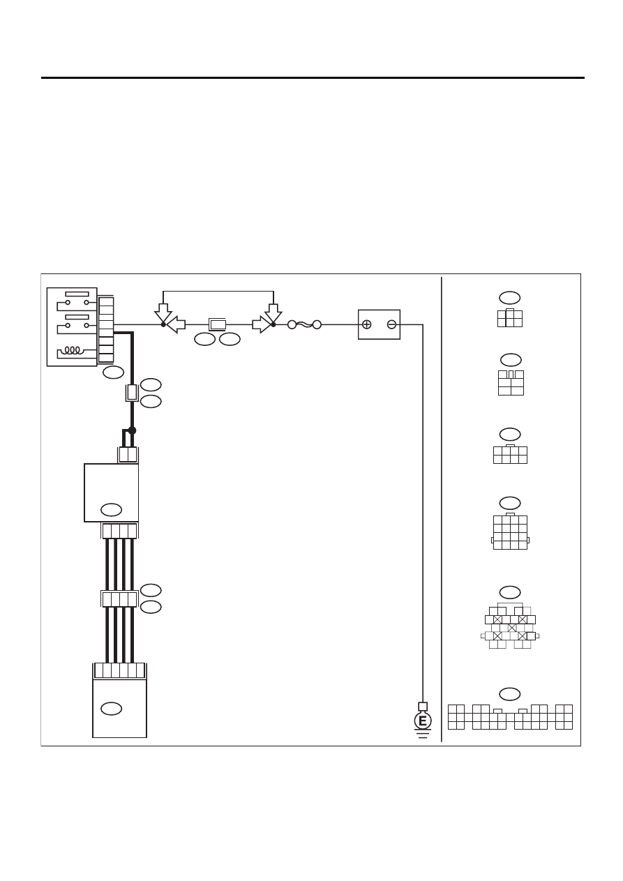
• WIRING DIAGRAM:
EN-01134
F44
B61
6
RHD
RHD
20
6
5
19
B21
E2
ECM
2
5
6
3
4
1
3
4
1
2
IDLE
AIR CONTROL
SOLENOID
VALVE
E7
B22
E3
B47
B134
B47
3
4
1
2
5
6
B134
1 2
3 4
5 6
7 8
9 10 11 12 13 14 15 16 17 18 19 20 21 22 23
24 25
26 27 28 29
30 31 32 33
34 35
B22
1 2 3 4
5 6 7 8
9 10 11 12
13 14 15 16
E7
1
3
4 5 6
2
B21
1 2
3 4
5
6 7
8
9 10
11 12
13
14 15
16
17 18
19 20
SBF-5
BATTERY
MAIN RELAY
1
2
3
5
4
6
1
1 2 3 4
5 6 7 8
F44
LHD
LHD

EN(H4SO)-289
ENGINE (DIAGNOSTICS)
DIAGNOSTIC PROCEDURE WITH DIAGNOSTIC TROUBLE CODE (DTC)
Step
Value
Yes
No
1
CHECK ANY OTHER DTC ON DISPLAY.
Does the Subaru Select Monitor or OBD-II
general scan tool indicate DTC P1511, P1513,
P1515 and P1517 at same time?
Indicated at same time.
2
CHECK GROUND CIRCUIT FOR ECM.
1) Turn ignition switch to OFF.
2) Measure resistance between ECM connec-
tor and chassis ground.
Connector & terminal
(B134) No. 7 — Chassis ground:
Is the measured value less than the speci-
fied value?
5
Ω
Repair harness
and connector.
NOTE:
In this case, repair
the following:
• Open circuit in
harness between
ECM connector
and engine ground
terminal
• Poor contact in
ECM connector
• Poor contact in
coupling connector
3
CHECK HARNESS BETWEEN ECM AND
IDLE AIR CONTROL SOLENOID VALVE
CONNECTOR.
1) Turn ignition switch to OFF.
2) Disconnect connector from idle air control
solenoid valve.
3) Turn ignition switch to ON.
4) Measure voltage between ECM connector
and chassis ground.
Connector & terminal
DTC P1511; (B134) No. 20 (+) — Chas-
sis ground (–):
DTC P1513; (B134) No. 6 (+) — Chassis
ground (–):
DTC P1515; (B134) No. 5 (+) — Chassis
ground (–):
DTC P1517; (B134) No. 19 (+) — Chas-
sis ground (–):
Does the measured value exceed the spec-
ified value?
10 V
Repair battery
short circuit in har-
ness between
ECM and idle air
control solenoid
valve connector.
After repair,
replace ECM.
<Ref. to
FU(H4SO)-45,
Engine Control
Module.>
Replace ECM.
<Ref. to
FU(H4SO)-45,
Engine Control
Module.>
EN(H4SO)-290
ENGINE (DIAGNOSTICS)
DIAGNOSTIC PROCEDURE WITH DIAGNOSTIC TROUBLE CODE (DTC)
CM:DTC P1518 — STARTER SWITCH CIRCUIT LOW INPUT —
• DTC DETECTING CONDITION:
• Two consecutive driving cycles with fault
• TROUBLE SYMPTOM:
• Failure of engine to start
CAUTION:
After repair or replacement of faulty parts, conduct Clear Memory Mode<Ref. to EN(H4SO)-47, OPER-
ATION, Clear Memory Mode.> and Inspection Mode <Ref. to EN(H4SO)-40, OPERATION, Inspection
Mode.> .
EN(H4SO)-291
ENGINE (DIAGNOSTICS)
DIAGNOSTIC PROCEDURE WITH DIAGNOSTIC TROUBLE CODE (DTC)
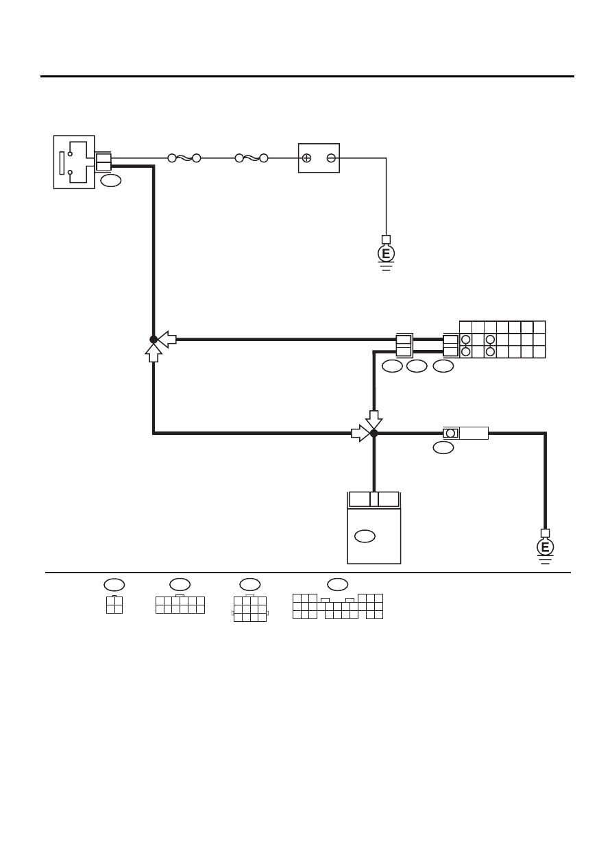
• WIRING DIAGRAM:
EN-01118
12
INHIBITOR SWITCH
STARTER
MOTOR
7
P
R
N
D
3
2
1
SBF-4
SBF-1
B14
B72
12
11
T7
T3
B12
1
3
IGNITION
SWITCH
AT
MT
AT
MT
T7
1 2 3 4 5 6
7 8 9 10 11 12
B72
3 4
1 2
20
B136
ECM
BATTERY
B12
1 2 3 4
5 6 7 8
9 10 11 12
B136
5 6
7
2
1
9
8
4
3
23
21 22
24
10 11 12 13 14
25 26
15 16 17
18 19 20
Нет комментариевНе стесняйтесь поделиться с нами вашим ценным мнением.
Текст