Subaru Legacy III (2000-2003 year). Service manual — part 170

EN(H4SO)-292
ENGINE (DIAGNOSTICS)
DIAGNOSTIC PROCEDURE WITH DIAGNOSTIC TROUBLE CODE (DTC)
Step
Value
Yes
No
1
CHECK OPERATION OF STARTER MOTOR.
Does starter motor operate when turning igni-
tion switch to “ST”?
NOTE:
Place the inhibitor switch in the “P” or “N” posi-
tion.
Operates.
Repair harness
and connector.
NOTE:
In this case, repair
the following:
• Open or ground
short circuit in har-
ness between
ECM and starter
motor connector.
• Poor contact in
ECM connector.
Check starter
motor circuit. <Ref.
to EN(H4SO)-64,
STARTER
MOTOR CIR-
CUIT, Diagnostics
for Engine Start-
ing Failure.>
EN(H4SO)-293
ENGINE (DIAGNOSTICS)
DIAGNOSTIC PROCEDURE WITH DIAGNOSTIC TROUBLE CODE (DTC)
MEMO:
EN(H4SO)-294
ENGINE (DIAGNOSTICS)
DIAGNOSTIC PROCEDURE WITH DIAGNOSTIC TROUBLE CODE (DTC)
CN:DTC P1560 — BACK-UP VOLTAGE CIRCUIT MALFUNCTION —
• DTC DETECTING CONDITION:
• Immediately at fault recognition
CAUTION:
After repair or replacement of faulty parts, conduct Clear Memory Mode<Ref. to EN(H4SO)-47, OPER-
ATION, Clear Memory Mode.> and Inspection Mode <Ref. to EN(H4SO)-40, OPERATION, Inspection
Mode.> .
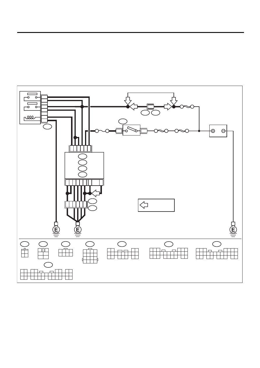
• WIRING DIAGRAM:
EN-01119
F44
B61
6
RHD
RHD
B9
C21
C23
B1
C12
B2
E3
B22
A7
A35
C26
B21
D14
C19
13
15
14
16
B47
BATTERY
MAIN RELAY
1
2
3
5
6
4
SBF-5
SBF-4
SBF-1
3
1
B72
IGNITION
SWITCH
ECM
B134
A :
B135
B :
B136
C :
B137
D :
C5
8
5 6 7
8
2
1
9
4
3
10
24
22 23
25
11 12 13 14 15
26
27 28
16 17 18 19
20 21
B135
B134
1 2
3 4
5 6
7 8
9 10 11 12 13 14 15 16 17 18 19 20 21 22 23
24 25
26 27 28 29
30 31 32 33
34 35
B47
3
4
1
2
5
6
B72
3 4
1 2
B22
1 2 3 4
5 6 7 8
9 10 11 12
13 14 15 16
C16
NO. 11
1 2 3 4
5 6 7 8
F44
B136
5 6
7
2
1
9
8
4
3
23
21 22
24
10 11 12 13 14
25 26
15 16 17
18 19 20
B137
4
1
5
3
2
6
18
15
16
7 8 9 10 11
17
19 20
12 13
14
LHD
LHD
: LHD MT MODEL
*
*

EN(H4SO)-295
ENGINE (DIAGNOSTICS)
DIAGNOSTIC PROCEDURE WITH DIAGNOSTIC TROUBLE CODE (DTC)
Step
Value
Yes
No
1
CHECK INPUT SIGNAL FOR ECM.
1) Turn ignition switch to OFF.
2) Measure voltage between ECM and chas-
sis ground.
Connector & terminal
(B135) No. 9 (+) — Chassis ground (
−−−−
):
Does the measured value exceed the spec-
ified value?
10 V
Repair poor con-
tact in ECM con-
nector.
2
CHECK HARNESS BETWEEN ECM AND
MAIN FUSE BOX CONNECTOR.
1) Disconnect connector from ECM.
2) Measure resistance of harness between
ECM and chassis ground.
Connector & terminal
(B135) No. 9 — Chassis ground:
Does the measured value exceed the spec-
ified value?
1 M
Ω
Repair ground
short circuit in har-
ness between
ECM connector
and battery termi-
nal.
3
CHECK FUSE SBF-5.
Is fuse blown?
Fuse is brown.
Replace fuse.
Repair harness
and connector.
NOTE:
In this case, repair
the following:
• Open circuit in
harness between
ECM and battery
• Poor contact in
ECM connector
• Poor contact in
battery terminal
Нет комментариевНе стесняйтесь поделиться с нами вашим ценным мнением.
Текст