Subaru Legacy III (2000-2003 year). Service manual — part 167
EN(H4SO)-280
ENGINE (DIAGNOSTICS)
DIAGNOSTIC PROCEDURE WITH DIAGNOSTIC TROUBLE CODE (DTC)
CC:DTC P1498 — EGR SOLENOID VALVE SIGNAL #4 CIRCUIT MALFUNCTION
(LOW INPUT) —
• DTC DETECTING CONDITION:
• Immediately at fault recognition
• TROUBLE SYMPTOM:
• Erroneous idling
• Engine stalls.
• Engine breathing
CAUTION:
After repair or replacement of faulty parts, conduct Clear Memory Mode<Ref. to EN(H4SO)-47, OPER-
ATION, Clear Memory Mode.> and Inspection Mode <Ref. to EN(H4SO)-40, OPERATION, Inspection
Mode.> .
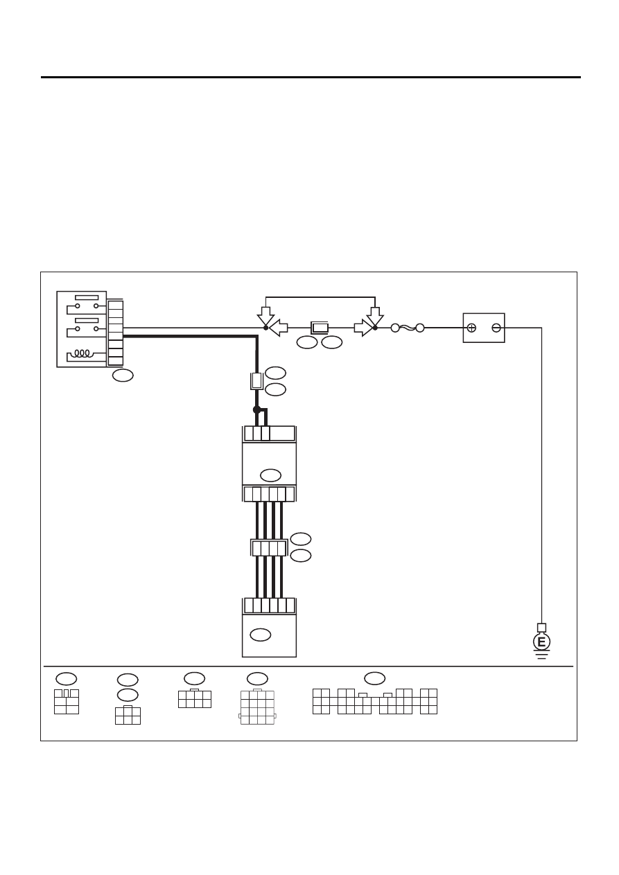
• WIRING DIAGRAM:
EN-01129
F44
B61
6
RHD
RHD
BATTERY
SBF-5
B47
MAIN RELAY
1
2
3
5
4
6
F44
1 2 3 4
5 6 7 8
1
6
3
4
1
B22
E3
E58
B328
EGR
SOLENOID
VALVE
2
5
E18
5
6
4
3
ECM
18
17
16
15
B134
B22
1 2 3 4
5 6 7 8
9 10 11 12
13 14 15 16
B47
3
4
5
6
1
2
LHD
LHD
E18
B328
1
3
4 5 6
2
B134
1 2
3 4
5 6
7 8
9 10 11 12 13 14 15 16 17 18 19 20 21 22 23
24 25
26 27 28 29
30 31 32 33
34 35

EN(H4SO)-281
ENGINE (DIAGNOSTICS)
DIAGNOSTIC PROCEDURE WITH DIAGNOSTIC TROUBLE CODE (DTC)
Step
Value
Yes
No
1
CHECK POWER SUPPLY TO EGR SOLE-
NOID VALVE.
1) Turn ignition switch to OFF.
2) Disconnect connector from EGR solenoid
valve.
3) Turn ignition switch to ON.
4) Measure voltage between EGR solenoid
valve connector and engine ground.
Connector & terminal
(E18) No. 2 (+) - Engine ground (-):
(E18) No. 5 (+) - Engine ground (-):
Does the measured value exceed the spec-
ified value?
10 V
Repair harness
and connector.
NOTE:
In this case, repair
the following:
• Open circuit in
harness between
EGR solenoid
valve and main
relay connector
• Poor contact in
coupling connector
2
CHECK HARNESS BETWEEN ECM AND
EGR SOLENOID VALVE CONNECTOR.
1) Turn ignition switch to OFF.
2) Measure resistance between ECM and
EGR solenoid valve connector.
Connector & terminal
DTC P1492; (B134) No. 18 - (E18) No. 6:
DTC P1494; (B134) No. 17 - (E18) No. 1:
DTC P1496; (B134) No. 16 - (E18) No. 4:
DTC P1498; (B134) No. 15 - (E18) No. 3:
Is the measured value less than the speci-
fied value?
1
Ω
Repair harness
and connector.
NOTE:
In this case, repair
the following:
• Open circuit in
harness between
ECM and EGR
solenoid valve
connector
• Poor contact in
coupling connector
3
CHECK HARNESS BETWEEN ECM AND
EGR SOLENOID VALVE CONNECTOR.
1) Disconnect connector from ECM.
2) Measure resistance between ECM connec-
tor and chassis ground.
Connector & terminal
DTC P1492; (B134) No. 18 - Chassis
ground:
DTC P1494; (B134) No. 17 - Chassis
ground:
DTC P1496; (B134) No. 16 - Chassis
ground:
DTC P1498; (B134) No. 15 - Chassis
ground:
Does the measured value exceed the spec-
ified value?
1 M
Ω
Repair ground
short circuit
between ECM and
EGR solenoid
valve connector.
4
CHECK POOR CONTACT.
Check poor contact between ECM connector
and EGR solenoid valve connector.
Is there poor contact of ECM connector or
EGR solenoid valve connector?
There is poor contact.
Repair poor con-
tact of ECM con-
nector or EGR
solenoid valve
connector.
Replace EGR
solenoid valve.
<Ref. to
FU(H4SO)-35,
EGR Valve.>

EN(H4SO)-282
ENGINE (DIAGNOSTICS)
DIAGNOSTIC PROCEDURE WITH DIAGNOSTIC TROUBLE CODE (DTC)
CD:DTC P1499 — EGR SOLENOID VALVE SIGNAL #4 CIRCUIT MALFUNCTION
(HIGH INPUT) —
• DTC DETECTING CONDITION:
• Immediately at fault recognition
• TROUBLE SYMPTOM:
• Erroneous idling
• Engine stalls.
• Engine breathing
CAUTION:
After repair or replacement of faulty parts, conduct Clear Memory Mode<Ref. to EN(H4SO)-47, OPER-
ATION, Clear Memory Mode.> and Inspection Mode <Ref. to EN(H4SO)-40, OPERATION, Inspection
Mode.> .
• WIRING DIAGRAM:
EN-01129
F44
B61
6
RHD
RHD
BATTERY
SBF-5
B47
MAIN RELAY
1
2
3
5
4
6
F44
1 2 3 4
5 6 7 8
1
6
3
4
1
B22
E3
E58
B328
EGR
SOLENOID
VALVE
2
5
E18
5
6
4
3
ECM
18
17
16
15
B134
B22
1 2 3 4
5 6 7 8
9 10 11 12
13 14 15 16
B47
3
4
5
6
1
2
LHD
LHD
E18
B328
1
3
4 5 6
2
B134
1 2
3 4
5 6
7 8
9 10 11 12 13 14 15 16 17 18 19 20 21 22 23
24 25
26 27 28 29
30 31 32 33
34 35

EN(H4SO)-283
ENGINE (DIAGNOSTICS)
DIAGNOSTIC PROCEDURE WITH DIAGNOSTIC TROUBLE CODE (DTC)
Step
Value
Yes
No
1
CHECK ANY OTHER DTC ON DISPLAY.
Is there any DTC on display?
Other DTC indicated on dis-
play.
2
CHECK ECM GROUND CIRCUIT.
1) Turn ignition switch to OFF.
2) Measure resistance between ECM connec-
tor and chassis ground.
Connector & terminal
(B134) No. 7 - Chassis ground:
(B137) No. 14 - Chassis ground:
(B135) No. 21 - Chassis ground:
Is the measured value less than the speci-
fied value?
5 Ω
Repair harness
and connector.
NOTE:
In this case, repair
the following:
• Open circuit in
harness between
ECM connector
and engine ground
• Poor contact in
ECM connector
• Poor contact in
coupling connector
3
CHECK HARNESS BETWEEN ECM AND
EGR SOLENOID VALVE CONNECTOR.
1) Turn ignition switch to OFF.
2) Disconnect connector from EGR solenoid
valve.
3) Turn ignition switch to ON.
4) Measure voltage between ECM connector
and chassis ground.
Connector & terminal
DTC P1493; (B134) No. 18 - Chassis
ground:
DTC P1495; (B134) No. 17 - Chassis
ground:
DTC P1497; (B134) No. 16 - Chassis
ground:
DTC P1499; (B134) No. 15 - Chassis
ground:
Does the measured value exceed the spec-
ified value?
10 V
Repair ground
short circuit
between ECM and
EGR solenoid
valve connector.
After completion of
repair, replace
ECM. <Ref. to
FU(H4SO)-45,
Engine Control
Module.>
Replace ECM.
<Ref. to
FU(H4SO)-45,
Engine Control
Module.>
Нет комментариевНе стесняйтесь поделиться с нами вашим ценным мнением.
Текст