Subaru Legacy III (2000-2003 year). Service manual — part 178
FU(H4SOw/oOBD)-18
FUEL INJECTION (FUEL SYSTEMS)
INTAKE MANIFOLD
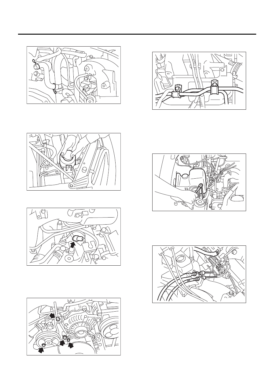
11) Connect PCV hose to intake manifold.
12) Connect spark plug cords to spark plugs.
13) Install power steering pump and tank on brack-
ets.
(1) Install power steering tank on bracket.
(2) Connect connector to power steering pump
switch.
(3) Tighten bolts which install power steering
pump on bracket.
Tightening torque:
22 N·m (2.2 kgf-m, 16 ft-lb)
(4) Install power steering pipes onto right side
intake manifold protector.
(5) Install front V-belt.
<Ref. to ME(H4SO)-42, INSTALLATION, V-
belt.>
(6) Install resonator chamber.
Tightening torque:
33 N·m (3.4 kgf-m, 24.6 ft-lb)
14) Connect accelerator cable (A).
<Ref. to SP(H4SO)-10, INSTALLATION, Accelera-
tor Control Cable.>
15) Connect cruise control cable (B). (With cruise
control models)
16) Install air intake duct and air cleaner assembly.
<Ref. to IN(H4SO)-7, INSTALLATION, Air Intake
Duct.> and <Ref. to IN(H4SO)-6, INSTALLATION,
Air Cleaner Case.>
FU-00719
FU-00429
FU-00428
FU-00139
FU-00718
FU-00261
FU-00715
( A )
( B )
FU(H4SOw/oOBD)-19
FUEL INJECTION (FUEL SYSTEMS)
INTAKE MANIFOLD
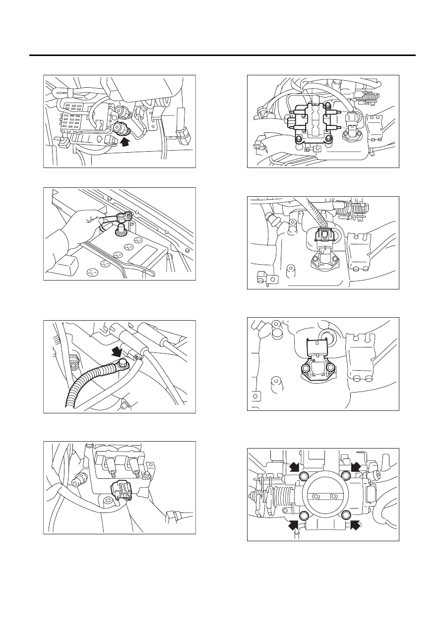
17) Connect connector to fuel pump relay.
18) Connect battery ground cable.
C: DISASSEMBLY
1) Disconnect engine ground terminal from intake
manifold.
2) Disconnect connector from ignition coil and igni-
tor assembly.
3) Remove ignition coil and ignitor assembly.
4) Disconnect connector from intake air tempera-
ture and pressure sensor.
5) Remove intake air temperature and pressure
sensor from intake manifold.
6) Disconnect connectors from throttle position
sensor and idle air control solenoid valve.
7) Remove throttle body.
FU-00431
FU-00009
FU-00263
FU-00721
FU-00722
FU-00723
FU-00724
FU-00725
FU(H4SOw/oOBD)-20
FUEL INJECTION (FUEL SYSTEMS)
INTAKE MANIFOLD
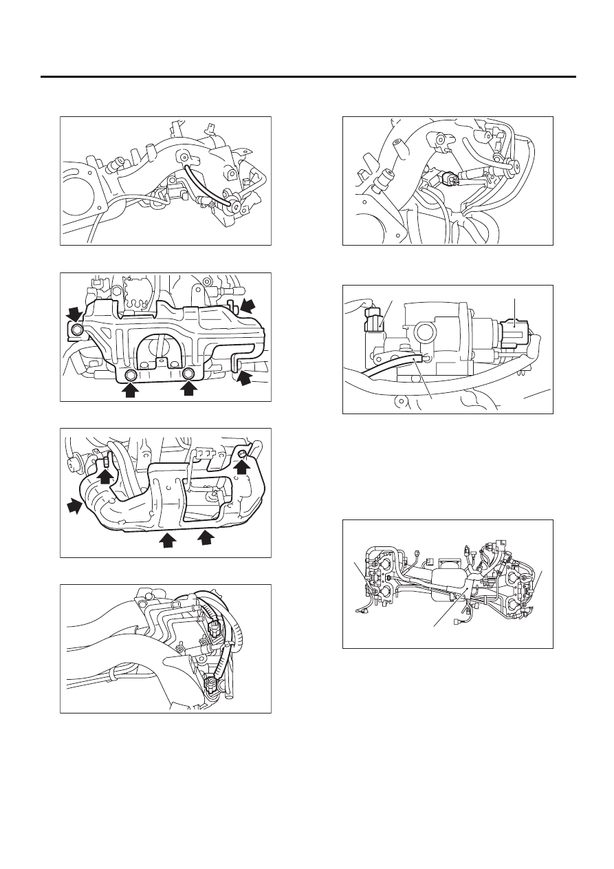
8) Disconnect pressure regulator vacuum hose
from intake manifold.
9) Remove fuel pipe protector LH.
10) Remove fuel pipe protector RH.
11) Disconnect connectors from fuel injectors.
12) Disconnect connector from purge control sole-
noid valve.
13) Disconnect air by-pass hose from purge control
solenoid valve.
14) Remove harness bands (A) and harness brack-
et (B) which hold engine harness onto intake man-
ifold.
15) Remove engine harness from intake manifold.
FU-00265
FU-00266
FU-00726
FU-00727
(A) Throttle position sensor
(B) Idle air control solenoid valve
(C) Air by-pass hose
FU-00728
FU-00716
( B )
( A )
( C )
FU-00795
( A )
( A )
( B )
FU(H4SOw/oOBD)-21
FUEL INJECTION (FUEL SYSTEMS)
INTAKE MANIFOLD
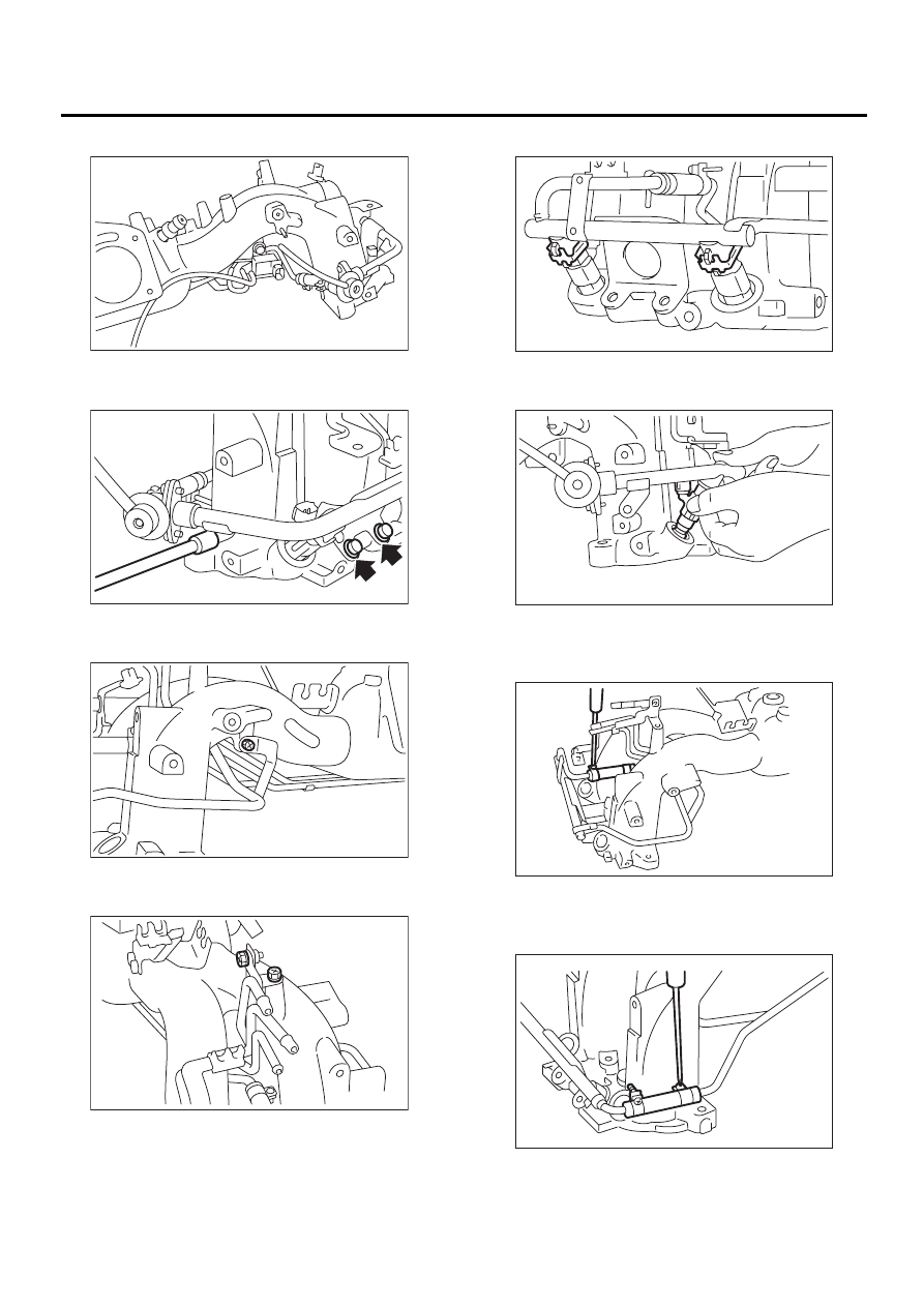
16) Remove purge control solenoid valve.
17) Remove bolt which installs injector pipe on in-
take manifold as shown in figure.
18) Remove bolt which installs injector pipe on in-
take manifold.
19) Remove two bolts which hold fuel pipes on the
left side of intake manifold.
20) Remove fuel injectors.
(1) Remove fuel injector securing clip.
(2) Remove fuel injector while lifting up fuel in-
jector pipe.
21) Loosen clamp which holds front left side fuel
hose to injector pipe and remove the pipe from
clamp.
22) Loosen clamp which holds front right side fuel
hose to injector pipe and remove the pipe from
clamp.
FU-00730
FU-00272
FU-00731
FU-00732
FU-00733
FU-00276
FU-00734
FU-00279
Нет комментариевНе стесняйтесь поделиться с нами вашим ценным мнением.
Текст