Subaru Legacy III (2000-2003 year). Service manual — part 176
FU(H4SOw/oOBD)-10
FUEL INJECTION (FUEL SYSTEMS)
GENERAL DESCRIPTION
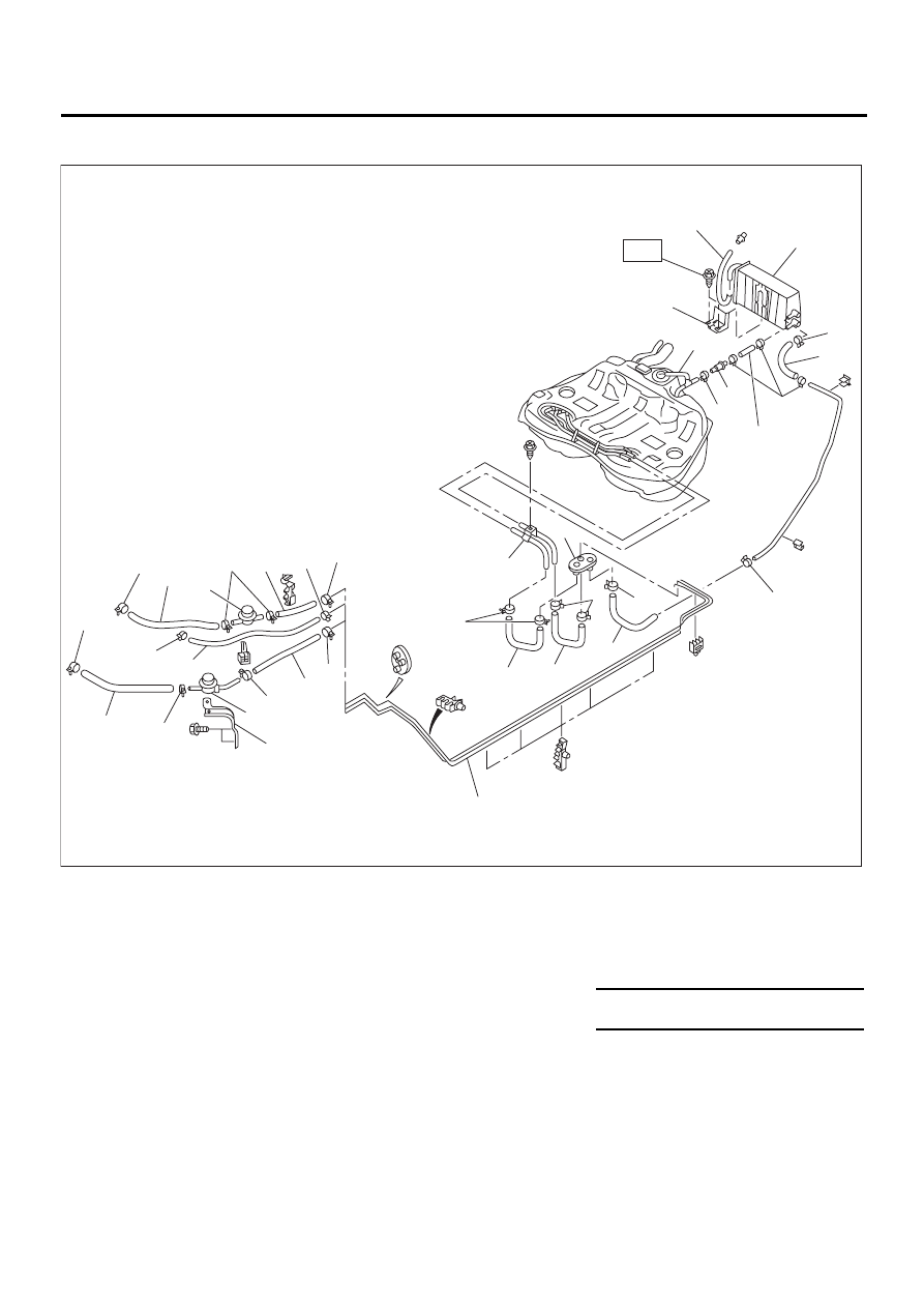
5. FUEL LINE
(1) Clamp
(10) Two-way valve
(19) Dumper valve (Delivery)
(2) Fuel delivery hose A
(11) Canister hose B
(20) Bracket
(3) Evaporation hose A
(12) Canister hose C
(21) Dumber valve (Return)
(4) Clip
(13) Canister bracket
(22) Fuel return hose B
(5) Fuel delivery hose B
(14) Fuel pipe ASSY
(6) Fuel return hose A
(15) Evaporation hose B
Tightening torque: N·m (kgf-m, ft-lb)
(7) Drain hose
(16) Fuel return hose C
T: 7.4
±±±±
2.0 (0.75
±±±±
0.2, 5.4
±±±±
1.4)
(8) Canister
(17) Fuel delivery hose C
(9) Canister hose A
(18) Grommet
FU-00713
( 1 )
( 1 )
( 1 )
( 1 )
( 1 )
( 1 )
( 1 )
( 1 )
( 1 )
( 1 )
( 1 )
( 1 )
( 1 )
( 1 )
( 2 )
( 3 )
( 4 )
( 4 )
( 5 )
( 6 )
( 7 )
( 8 )
( 9 )
(10)
(11)
(12)
(13)
(14)
(14)
(15)
(16)
(17)
(18)
(19)
(20)
(21)
(22)
T
FU(H4SOw/oOBD)-11
FUEL INJECTION (FUEL SYSTEMS)
GENERAL DESCRIPTION
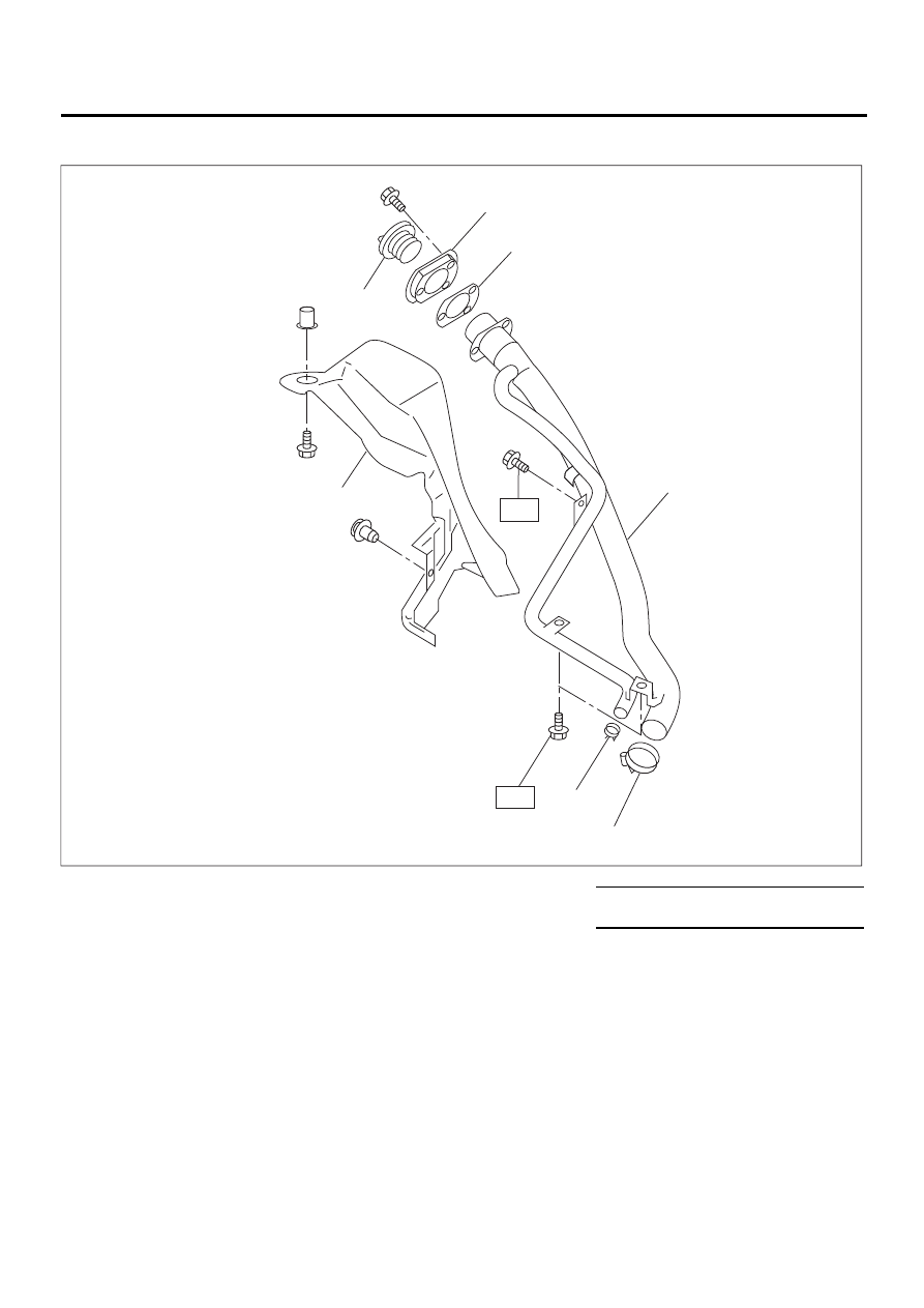
6. FUEL FILLER PIPE
(1) Fuel filler pipe ASSY
(5) Filler ring
Tightening torque: N·m (kgf-m, ft-lb)
(2) Clip
(6) Filler cap
T: 7.4 (0.75, 5.4)
(3) Clamp
(7) Filler pipe protector
(4) Filler pipe packing
FU-00628
( 1 )
( 2 )
( 3 )
( 4 )
( 5 )
( 6 )
( 7 )
T
T
FU(H4SOw/oOBD)-12
FUEL INJECTION (FUEL SYSTEMS)
GENERAL DESCRIPTION
C: CAUTION
• Wear working clothing, including a cap, protec-
tive goggles, and protective shoes during opera-
tion.
• Remove contamination including dirt and corro-
sion before removal, installation or disassembly.
• Keep the disassembled parts in order and pro-
tect them from dust or dirt.
• Before removal, installation or disassembly, be
sure to clarify the failure. Avoid unnecessary re-
moval, installation, disassembly, and replacement.
• Be careful not to burn your hands, because each
part on the vehicle is hot after running.
• Be sure to tighten fasteners including bolts and
nuts to the specified torque.
• Place shop jacks or safety stands at the specified
points.
• Before disconnecting electrical connectors of
sensors or units, be sure to disconnect ground ca-
ble from battery.
• Place “NO FIRE” signs near the working area.
• Be careful not to spill fuel on the floor.
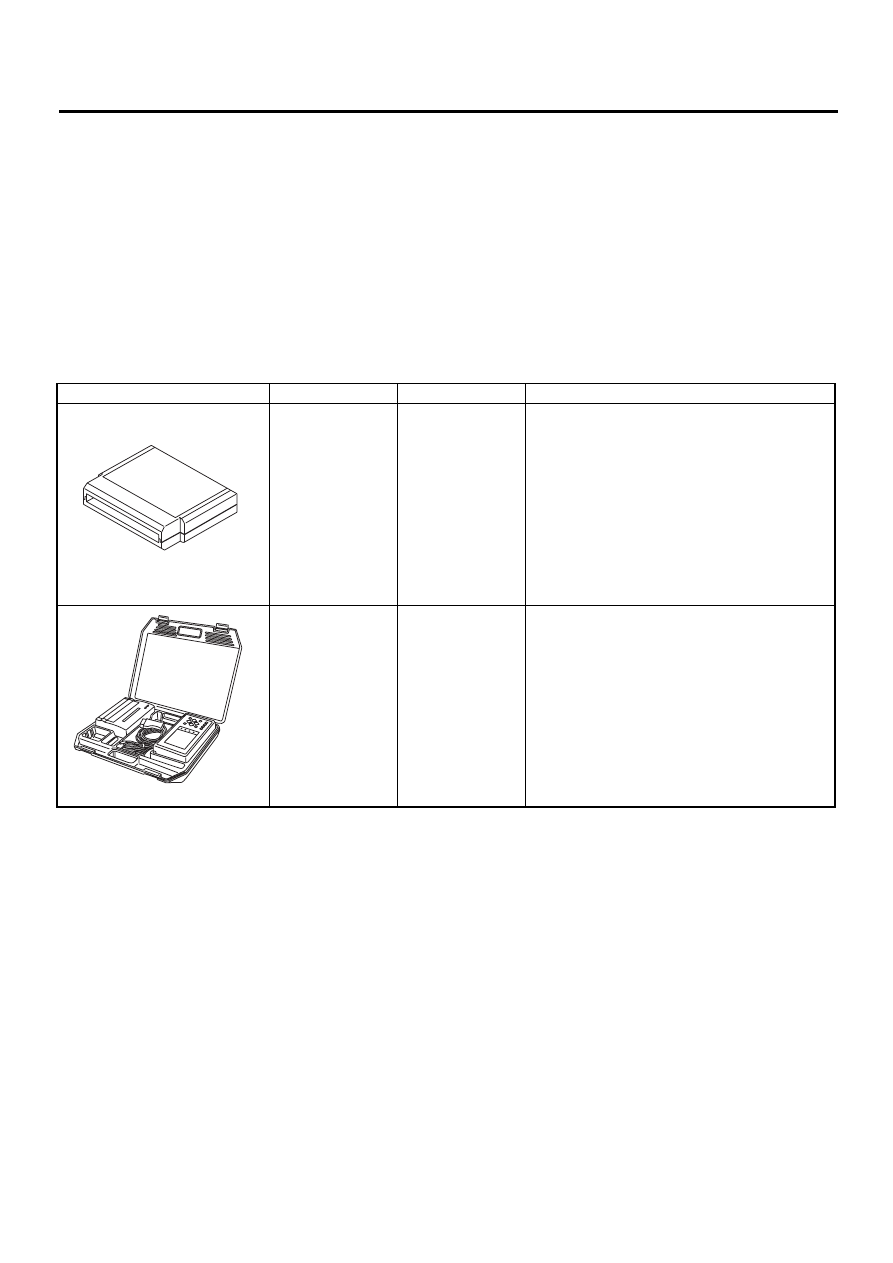
D: PREPARATION TOOL
ILLUSTRATION
TOOL NUMBER
DESCRIPTION
REMARKS
24082AA210
CARTRIDGE
Troubleshooting for electrical systems.
22771AA030
SELECT MONI-
TOR KIT
Troubleshooting for electrical systems.
• English: 22771AA030 (Without printer)
• German: 22771AA070 (Without printer)
• French: 22771AA080 (Without printer)
• Spanish: 22771AA090 (Without printer)
ST24082AA210
ST22771AA030
FU(H4SOw/oOBD)-13
FUEL INJECTION (FUEL SYSTEMS)
THROTTLE BODY
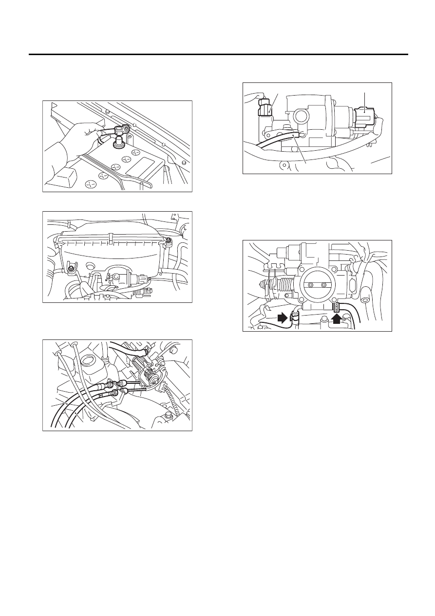
2. Throttle Body
A: REMOVAL
1) Disconnect battery ground cable.
2) Remove air cleaner case.
3) Disconnect accelerator cable (A).
4) Disconnect cruise control cable (B). (With cruise
control model)
5) Disconnect connectors from idle air control sole-
noid valve, throttle position sensor.
6) Disconnect air by-pass hose from purge control
solenoid valve.
7) Disconnect engine coolant hoses from throttle
body.
8) Remove bolts which install throttle body to intake
manifold.
B: INSTALLATION
Install in the reverse order of removal.
NOTE:
Always use a new gasket.
Tightening torque:
Throttle body;
22 N·m (2.2 kgf-m, 15.9 ft-lb)
Air cleaner case;
6.5 N·m (0.66 kgf-m, 4.8 ft-lb)
FU-00009
FU-00714
FU-00715
( A )
( B )
(A) Throttle position sensor
(B) Idle air control solenoid valve
(C) Air by-pass hose
FU-00716
( B )
( A )
( C )
FU-00717
Нет комментариевНе стесняйтесь поделиться с нами вашим ценным мнением.
Текст