Subaru Legacy III (2000-2003 year). Service manual — part 500
EN(H4DOSTC)-170
ENGINE (DIAGNOSTICS)
DIAGNOSTIC PROCEDURE WITH DIAGNOSTIC TROUBLE CODE (DTC)
AM:DTC P0851 — NEUTRAL SWITCH INPUT CIRCUIT LOW (AT MODEL) —
• DTC DETECTING CONDITION:
• Two consecutive driving cycles with fault
• TROUBLE SYMPTOM:
• Erroneous idling
CAUTION:
After repair or replacement of faulty parts, conduct Clear Memory Mode<Ref. to EN(H4DOSTC)-35,
OPERATION, Clear Memory Mode.> and Inspection Mode <Ref. to EN(H4DOSTC)-33, OPERATION,
Inspection Mode.> .
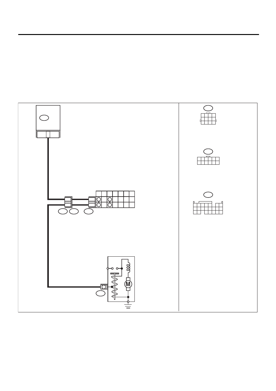
• WIRING DIAGRAM:
EN-01003
12
INHIBITOR SWITCH
7
P
R
N
D
3
2
1
12
11
T7
T3
B12
B14
B12
T7
1 2 3 4 5 6
7 8 9 10 11 12
8
B134
ECM
STARTER MOTOR
1 2 3 4
5 6 7 8
9 10 11 12
B134
1 2 3 4
10 11 12
19 20 21
13
5
6
14 15
7
8 9
16 17
18
22

EN(H4DOSTC)-171
ENGINE (DIAGNOSTICS)
DIAGNOSTIC PROCEDURE WITH DIAGNOSTIC TROUBLE CODE (DTC)
Step
Value
Yes
No
1
CHECK ANY OTHER DTC ON DISPLAY.
Is any other DTC displayed?
DTC indicated.
Inspect the rele-
vant DTC using
“List of Diagnos-
tics Trouble Code
(DTC)”. <Ref. to
EN(H4DOSTC)-
62, List of Diag-
nostic Trouble
Code (DTC).>
2
CHECK INPUT SIGNAL FOR ECM.
1) Turn ignition switch to ON.
2) Measure voltage between ECM and chas-
sis ground.
Connector & terminal
(B134) No. 8 (+) — Chassis ground (
−−−−
):
Is the measured value within the specified
value at except “N” and “P” position?
4.5 V — 5.5 V
Even if MI lights
up, the circuit has
returned to a nor-
mal condition at
this time.
3
CHECK HARNESS BETWEEN ECM AND
TRANSMISSION HARNESS CONNECTOR.
1) Turn ignition switch to OFF.
2) Disconnect connectors from ECM and
transmission harness connector (T3).
3) Measure resistance of harness between
ECM connector and chassis ground.
Connector & terminal
(B134) No. 8 — Chassis ground:
Does the measured value exceed the spec-
ified value?
1 M
Ω
Repair ground
short circuit in har-
ness between
ECM and trans-
mission harness
connector.
4
CHECK TRANSMISSION HARNESS CON-
NECTOR.
1) Disconnect connector from inhibitor switch.
2) Measure resistance of harness between
transmission harness connector and
engine ground.
Connector & terminal
(T3) No. 12 — Engine ground:
Does the measured value exceed the spec-
ified value?
1 M
Ω
Repair ground
short circuit in har-
ness between
transmission har-
ness and inhibitor
switch connector.
5
CHECK INHIBITOR SWITCH.
Measure resistance between inhibitor switch
connector receptacle's terminals in select lever
except for “N” position.
Terminals
No. 7 — No. 12:
Does the measured value exceed the specified
value at except “N” and “P” positions?
1 M
Ω
Replace inhibitor
switch. <Ref. to
AT-49, Inhibitor
Switch.>
6
CHECK SELECTOR CABLE CONNECTION.
Is there any fault in selector cable connection
to inhibitor switch?
There is a fault.
Repair selector
cable connection.
<Ref. to CS-12,
Select Cable.>
Contact SUBARU
distributor service.
NOTE:
Inspection by DTM
is required, be-
cause probable
cause is deteriora-
tion of multiple
parts.
EN(H4DOSTC)-172
ENGINE (DIAGNOSTICS)
DIAGNOSTIC PROCEDURE WITH DIAGNOSTIC TROUBLE CODE (DTC)
AN:DTC P0851 — NEUTRAL SWITCH INPUT CIRCUIT LOW (MT MODEL) —
• DTC DETECTING CONDITION:
• Two consecutive driving cycles with fault
• TROUBLE SYMPTOM:
• Erroneous idling
CAUTION:
After repair or replacement of faulty parts, conduct Clear Memory Mode<Ref. to EN(H4DOSTC)-35,
OPERATION, Clear Memory Mode.> and Inspection Mode <Ref. to EN(H4DOSTC)-33, OPERATION, In-
spection Mode.> .
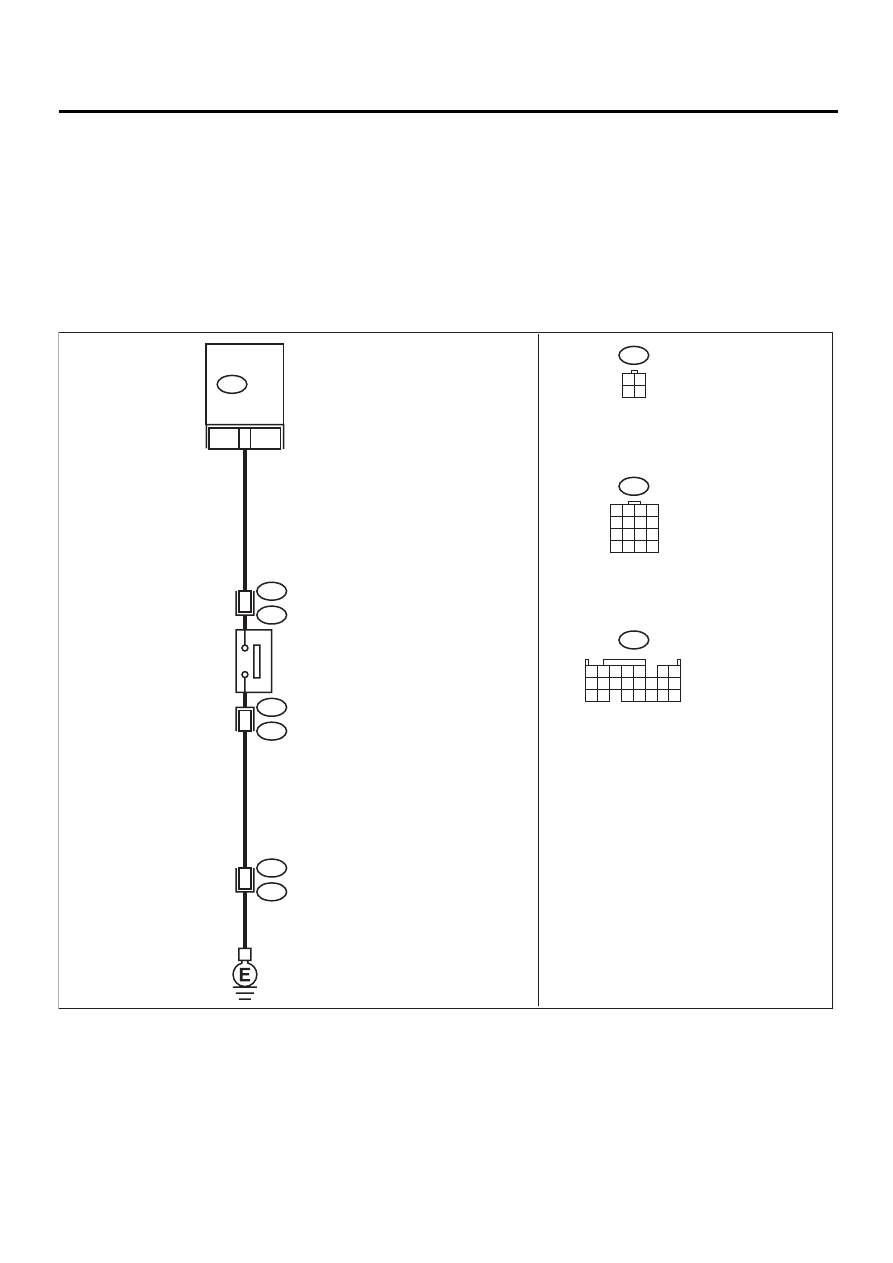
• WIRING DIAGRAM:
EN-01004
2
1
8
B134
ECM
NEUTRAL
POSITION
SWITCH
B128
T9
T9
B128
B22
E3
16
B128
B22
1 2 3 4
5 6 7 8
9 10 11 12
13 14 15 16
B134
3 4
1 2
1 2 3 4
10 11 12
19 20 21
13
5
6
14 15
7
8 9
16 17
18
22

EN(H4DOSTC)-173
ENGINE (DIAGNOSTICS)
DIAGNOSTIC PROCEDURE WITH DIAGNOSTIC TROUBLE CODE (DTC)
Step
Value
Yes
No
1
CHECK INPUT SIGNAL FOR ECM.
1) Turn ignition switch to ON.
2) Measure voltage between ECM and chas-
sis ground.
Connector & terminal
(B134) No. 8 (+) — Chassis ground (
−−−−
):
Does the measured value exceed the spec-
ified value in neutral position?
5 V
2
CHECK INPUT SIGNAL FOR ECM.
Measure voltage between ECM and chassis
ground.
Connector & terminal
(B134) No. 8 (+) — Chassis ground (
−−−−
):
Is the measured value less than the specified
value at except neutral position?
1 V
3
CHECK POOR CONTACT.
Check poor contact in ECM connector.
Is there poor contact in ECM connector?
There is poor contact.
Repair poor con-
tact in ECM con-
nector.
Contact SUBARU
distributor service.
NOTE:
Inspection by DTM
is required, be-
cause probable
cause is deteriora-
tion of multiple
parts.
4
CHECK NEUTRAL POSITION SWITCH.
1) Turn ignition switch to OFF.
2) Disconnect connector from transmission
harness.
3) Measure resistance between transmission
harness and connector terminals.
Connector & terminal
(T9) No. 1 — No. 2:
Does the measured value exceed the spec-
ified value in neutral position?
1 M
Ω
Repair short circuit
in transmission
harness or replace
neutral position
switch.
5
CHECK HARNESS BETWEEN ECM AND
NEUTRAL POSITION SWITCH CONNEC-
TOR.
1) Disconnect connector from ECM.
2) Measure resistance between ECM and
chassis ground.
Connector & terminal
(B134) No. 8 — Chassis ground:
Does the measured value exceed the spec-
ified value?
1 M
Ω
Repair ground
short circuit in har-
ness between
ECM and trans-
mission harness
connector.
6
CHECK POOR CONTACT.
Check poor contact in transmission harness
connector.
Is there poor contact in transmission harness
connector?
There is poor contact.
Repair poor con-
tact in transmis-
sion harness
connector.
Contact SUBARU
distributor service.
NOTE:
Inspection by DTM
is required, be-
cause probable
cause is deteriora-
tion of multiple
parts.
Нет комментариевНе стесняйтесь поделиться с нами вашим ценным мнением.
Текст