Subaru Legacy III (2000-2003 year). Service manual — part 498
EN(H4DOSTC)-162
ENGINE (DIAGNOSTICS)
DIAGNOSTIC PROCEDURE WITH DIAGNOSTIC TROUBLE CODE (DTC)
AI: DTC P0509 — IDLE CONTROL SYSTEM CIRCUIT HIGH —
• TROUBLE SYMPTOM:
• Erroneous idling
• Engine stalls.
• Engine breathing
CAUTION:
After repair or replacement of faulty parts, conduct Clear Memory Mode <Ref. to EN(H4DOSTC)-35,
OPERATION, Clear Memory Mode.> and Inspection Mode <Ref. to EN(H4DOSTC)-33, Inspection
Mode.> .
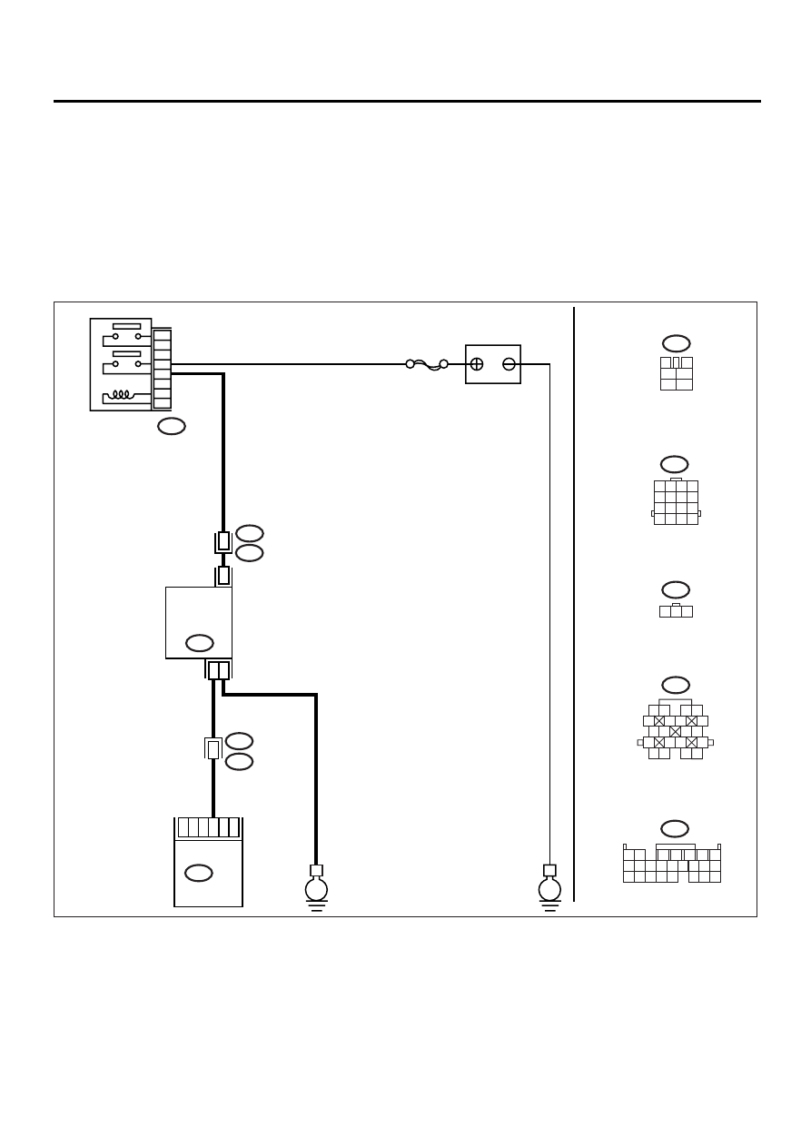
• WIRING DIAGRAM:
EN-00947
BATTERY
MAIN RELAY
E
E
6
4
5
3
2
1
10
IDLE
AIR CONTROL
SOLENOID
VALVE
1
3
E7
B47
B47
3
4
1
2
5
6
1 2
7
8 9
5
6
3
4
10 11 12
19 20 21
13 14 15 16
17 18
22 23 24
B136
B136 ECM
2
1
B22
E3
SBF-5
B22
E7
1 2 3
1 2
5
6 7
8
13
14 15
16
9 10
11 12
3 4
17 18
19 20
1 2 3 4
5 6 7 8
9 10 11 12
13 14 15 16
B21
E2
B21
12

EN(H4DOSTC)-163
ENGINE (DIAGNOSTICS)
DIAGNOSTIC PROCEDURE WITH DIAGNOSTIC TROUBLE CODE (DTC)
Step
Value
Yes
No
1
CHECK THROTTLE CABLE.
Does the throttle cable have play for adjust-
ment?
Cable has play correctly.
Adjust the throttle
cable. <Ref. to
SP(H4SO)-10,
Accelerator Con-
trol Cable.>
2
CHECK OUTPUT SIGNAL FROM ECM.
1) Turn the ignition switch to ON.
2) Measure the voltage between ECM and
chassis ground.
Connector & terminal
(B136) No. 10 (+) — Chassis ground (
−−−−
):
Does the measured value exceed the spec-
ified value?
10 V
3
CHECK OUTPUT SIGNAL FROM ECM.
1) Turn the ignition switch to OFF.
2) Disconnect the connector from idle air con-
trol solenoid valve.
3) Turn the ignition switch to ON.
4) Measure the voltage between ECM and
chassis ground.
Connector & terminal
(B136) No. 10 (+) — Chassis ground (
−−−−
):
Does the measured value exceed the spec-
ified value?
10 V
Repair the battery
short circuit in har-
ness between
ECM and idle air
control solenoid
valve connector.
After repair,
replace the ECM.
<Ref. to
FU(H4DOSTC)-
40, Engine Con-
trol Module.>
Replace the idle
air control solenoid
valve <Ref. to
FU(H4DOSTC)-
35, Idle Air Con-
trol Solenoid
Valve.> and
replace ECM
<Ref. to
FU(H4DOSTC)-
40, Engine Con-
trol Module.>.
4
CHECK OUTPUT SIGNAL FROM ECM.
Measure the voltage between ECM and chas-
sis ground.
Connector & terminal
(B136) No. 10 (+) — Chassis ground (
−−−−
):
Does the measured value change by shaking
harness and connector of ECM while monitor-
ing the value with voltage meter?
The value changes.
Repair the battery
short circuit in har-
ness between
ECM and idle air
control solenoid
valve connector.
After repair,
replace the ECM.
<Ref. to
FU(H4DOSTC)-
40, Engine Con-
trol Module.>
Contact SUBARU
distributor service.
NOTE:
Insepction by DTM
is required, be-
cause probable
cause is deteriora-
tion of multiple
parts.
EN(H4DOSTC)-164
ENGINE (DIAGNOSTICS)
DIAGNOSTIC PROCEDURE WITH DIAGNOSTIC TROUBLE CODE (DTC)
AJ:DTC P0512 — STARTER REQUEST CIRCUIT —
• TROUBLE SYMPTOM:
• Failure of engine to start
CAUTION:
After repair or replacement of faulty parts, conduct Clear Memory Mode <Ref. to EN(H4DOSTC)-35,
OPERATION, Clear Memory Mode.> and Inspection Mode <Ref. to EN(H4DOSTC)-33, Inspection
Mode.> .
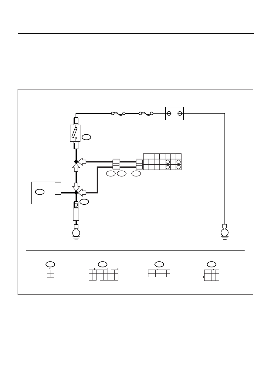
• WIRING DIAGRAM:
EN-00930
BATTERY
IGNITION
SWITCH
STARTER
MOTOR
SBF-4
SBF-1
B72
B72
B14
B134 ECM
E
E
1
3
16
3 4
1 2
B134
B12
T7
1 2 3 4
10 11 12
19 20 21
13
5
6
14 15
7
8 9
16 17
18
22
12
INHIBITOR SWITCH
7
P
R
N
D
3
2
1
12
11
T7
T3
B12
AT
AT
MT
MT
1 2 3 4 5 6
7 8 9 10 11 12
1 2 3 4
5 6 7 8
9 10 11 12

EN(H4DOSTC)-165
ENGINE (DIAGNOSTICS)
DIAGNOSTIC PROCEDURE WITH DIAGNOSTIC TROUBLE CODE (DTC)
Step
Value
Yes
No
1
CHECK OPERATION OF STARTER MOTOR.
NOTE:
Place the inhibitor switch in each position.
Does the starter motor operate when ignition
switch to “ON”?
Operates.
Repair the battery
short circuit in
starter motor cir-
cuit. After repair,
replace the ECM.
<Ref. to
FU(H4DOSTC)-
40, Engine Con-
trol Module.>
Check the starter
motor circuit.
<Ref. to
EN(H4DOSTC)-
52, STARTER
MOTOR CIR-
CUIT, Diagnostics
for Engine Start-
ing Failure.>
Нет комментариевНе стесняйтесь поделиться с нами вашим ценным мнением.
Текст