Subaru Legacy III (2000-2003 year). Service manual — part 499
EN(H4DOSTC)-166
ENGINE (DIAGNOSTICS)
DIAGNOSTIC PROCEDURE WITH DIAGNOSTIC TROUBLE CODE (DTC)
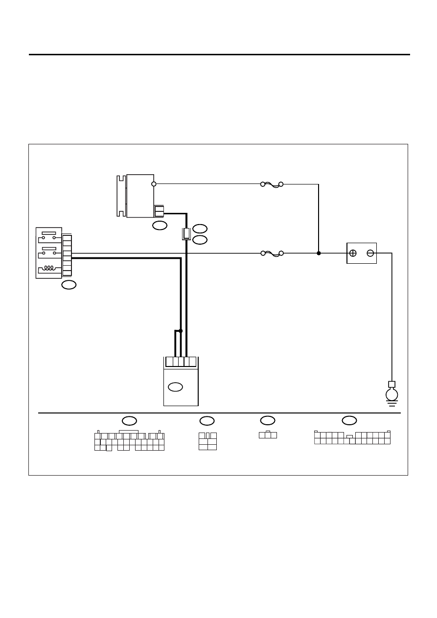
AK:DTC P0562 — SYSTEM VOLTAGE LOW —
• TROUBLE SYMPTOM:
• Charge warning light comes on.
CAUTION:
After repair or replacement of faulty parts, conduct Clear Memory Mode <Ref. to EN(H4DOSTC)-35,
OPERATION, Clear Memory Mode.> and Inspection Mode <Ref. to EN(H4DOSTC)-33, OPERATION, In-
spection Mode.>.
• WIRING DIAGRAM:
EN-00948
B137
B47
E
SBF-1
F26
F2
BATTERY
GENERATOR
MAIN RELAY
3
3
SBF-5
5
2
1
4
6
B47
3
4
1
2
5
6
B137 ECM
2
12
3
F2
F26
B100
21
1
2
7
8
9
5
6
3
4
10
11
12
19
20
21
29
30
31
13
14
15
16
17
27
28
18
22
23
24
25
26
1 2 3
3 4
1 2
8 9 10 11
12 13 14 15 16 17 18 19 20 21 22 23 24
5
6 7

EN(H4DOSTC)-167
ENGINE (DIAGNOSTICS)
DIAGNOSTIC PROCEDURE WITH DIAGNOSTIC TROUBLE CODE (DTC)
Step
Value
Yes
No
1
CHECK GENERATOR.
1) Start the engine.
2) Idling after warm-up.
3) Measure the voltage between generator B
terminal and chassis ground.
Terminal
Generator B terminal (+) — Chassis
ground (–):
Is the measured value less than the speci-
fied value?
10.8 V
Repair the genera-
tor. <Ref. to
SC(H4DOSTC)-
14, Generator.>
2
CHECK GENERATOR.
1) Run the engine at 5,000 rpm.
2) Measure the voltage between generator B
terminal and chassis gorund.
Terminal
Generator B terminal (+) — Chassis
ground (
−−−−
):
Is the measured value less than the speci-
fied value?
10.8 V
Repair the genera-
tor. <Ref. to
SC(H4DOSTC)-
14, Generator.>
3
CHECK BATTERY TERMINAL.
Turn the ignition switch to OFF.
Are the positive and negative battery terminals
tightly clamped?
Clamped tightly.
Tighten the clamp
of terminal.
4
CHECK INPUT VOLTAGE OF ECM.
1) Run the engine at idle.
2) Measure the voltage between ECM con-
nector and chassis ground.
Connector & terminal
(B136) No. 1 (+) — Chassis ground (
−−−−
):
(B136) No. 2 (+) — Chassis ground (
−−−−
):
Is the measured value less than the speci-
fied value?
10.8 V
Repair the har-
ness connector
between battery,
main relay and
ECM.
5
CHECK POOR CONTACT IN CONNECTORS.
Is there poor contact in connectors between
generator, battery and ECM?
There is poor contact.
Repair the con-
nector.
6
CHECK ECM.
1) Connect all connectors.
2) Erase the memory. <Ref. to
EN(H4DOSTC)-35, Clear Memory Mode.>
3) Perform the inspection mode. <Ref. to
EN(H4DOSTC)-33, Inspection Mode.>
4) Read out the DTC. <Ref. to
EN(H4DOSTC)-32, Read Diagnostic Trou-
ble Code.>
Is the same DTC as in the current diagno-
sis still being output?
DTC indicated.
Replace the gen-
erator.
7
CHECK ANY OTHER DTCs APPEARANCE.
Are other DTCs being output?
DTCs indicated.
Proceed with the
diagnosis corre-
sponding to the
DTC.
A temporary poor
contact.

EN(H4DOSTC)-168
ENGINE (DIAGNOSTICS)
DIAGNOSTIC PROCEDURE WITH DIAGNOSTIC TROUBLE CODE (DTC)
AL:DTC P0563 — SYSTEM VOLTAGE HIGH —
• TROUBLE SYMPTOM:
• Charge warning light comes on.
CAUTION:
After repair or replacement of faulty parts, conduct Clear Memory Mode <Ref. to EN(H4DOSTC)-35,
OPERATION, Clear Memory Mode.> and Inspection Mode <Ref. to EN(H4DOSTC)-33, OPERATION, In-
spection Mode.>.
• WIRING DIAGRAM:
EN-00948
B137
B47
E
SBF-1
F26
F2
BATTERY
GENERATOR
MAIN RELAY
3
3
SBF-5
5
2
1
4
6
B47
3
4
1
2
5
6
B137 ECM
2
12
3
F2
F26
B100
21
1
2
7
8
9
5
6
3
4
10
11
12
19
20
21
29
30
31
13
14
15
16
17
27
28
18
22
23
24
25
26
1 2 3
3 4
1 2
8 9 10 11
12 13 14 15 16 17 18 19 20 21 22 23 24
5
6 7

EN(H4DOSTC)-169
ENGINE (DIAGNOSTICS)
DIAGNOSTIC PROCEDURE WITH DIAGNOSTIC TROUBLE CODE (DTC)
Step
Value
Yes
No
1
CHECK GENERATOR.
1) Start the engine.
2) Idling after warm-up.
3) Measure the voltage between generator B
terminal and chassis ground.
Terminal
Generator B terminal (+) — Chassis
ground (–):
Does the measured value exceed the spec-
ified value?
16.2 V
Repair the genera-
tor. <Ref. to
SC(H4DOSTC)-
14, Generator.>
2
CHECK GENERATOR.
1) Run the engine at 5,000 rpm.
2) Measure the voltage between generator B
terminal and chassis gorund.
Terminal
Generator B terminal (+) — Chassis
ground (
−−−−
):
Does the measured value exceed the spec-
ified value?
16.2 V
Repair the genera-
tor. <Ref. to
SC(H4DOSTC)-
14, Generator.>
3
CHECK BATTERY TERMINAL.
Turn the ignition switch to OFF.
Are the positive and negative battery terminals
tightly clamped?
Clamped tightly.
Tighten the clamp
of terminal.
4
CHECK INPUT VOLTAGE OF ECM.
1) Run the engine at idle.
2) Measure the voltage between ECM con-
nector and chassis ground.
Connector & terminal
(B136) No. 1 (+) — Chassis ground (
−−−−
):
(B136) No. 2 (+) — Chassis ground (
−−−−
):
Does the measured value exceed the spec-
ified value?
16.2 V
Repair the har-
ness connector
between battery,
main relay and
ECM.
5
CHECK POOR CONTACT IN CONNECTORS.
Is there poor contact in connectors between
generator, battery and ECM?
There is poor contact.
Repair the con-
nector.
6
CHECK ECM.
1) Connect all connectors.
2) Erase the memory. <Ref. to
EN(H4DOSTC)-35, Clear Memory Mode.>
3) Perform the inspection mode. <Ref. to
EN(H4DOSTC)-33, Inspection Mode.>
4) Read out the DTC. <Ref. to
EN(H4DOSTC)-32, Read Diagnostic Trou-
ble Code.>
Is the same DTC as in the current diagno-
sis still being output?
DTC indicated.
Replace the gen-
erator.
7
CHECK ANY OTHER DTCs APPEARANCE.
Are other DTCs being output?
DTCs indicated.
Proceed with the
diagnosis corre-
sponding to the
DTC.
A temporary poor
contact.
Нет комментариевНе стесняйтесь поделиться с нами вашим ценным мнением.
Текст