Subaru Legacy III (2000-2003 year). Service manual — part 770

VDC-116
VDC (DIAGNOSTICS)
DIAGNOSTICS CHART WITH DIAGNOSIS CONNECTOR
7
CHECK HARNESS OF STEERING ANGLE
SENSOR.
1) Connect connector to steering angle sen-
sor.
2) Disconnect connector from VDCCM.
3) Measure resistance between VDCCM con-
nector terminals.
Connector & terminal
(F87) No. 81 — No. 83:
Is the measured value within the specified
range?
114 — 126
Ω
Repair harness
between steering
angle sensor and
VDCCM.
8
CHECK STEERING ANGLE SENSOR.
1) Turn ignition switch to OFF.
2) Connect all connectors.
3) Erase the memory.
4) Perform inspection mode.
5) Read out the diagnostic trouble code.
Is the same diagnostic trouble code as in
the current diagnosis still being output?
Same DTC indicated.
9
CHECK ANY OTHER DIAGNOSTIC TROU-
BLE CODES APPEARANCE.
Are other diagnostic trouble codes being out-
put?
Other DTC indicated.
Proceed with the
diagnosis corre-
sponding to the
diagnostic trouble
code.
A temporary poor
contact.
10
CHECK VDCCM.
1) Turn ignition switch to OFF.
2) Replace steering angle sensor.
3) Erase the memory.
4) Perform inspection mode.
5) Read out the diagnostic trouble code.
Is the same diagnostic trouble code as in
the current diagnosis still being output?
Same DTC indicated.
Replace VDCCM.
<Ref. to VDC-8,
VDC Control Mod-
ule (VDCCM).>
11
CHECK ANY OTHER DIAGNOSTIC TROU-
BLE CODES APPEARANCE.
Are other diagnostic trouble codes being out-
put?
Other DTC indicated.
Proceed with the
diagnosis corre-
sponding to the
diagnostic trouble
code.
The original steer-
ing angle sensor
has been faulty.
Step
Value
Yes
No
VDC-117
VDC (DIAGNOSTICS)
DIAGNOSTICS CHART WITH DIAGNOSIS CONNECTOR
MEMO:
VDC-118
VDC (DIAGNOSTICS)
DIAGNOSTICS CHART WITH DIAGNOSIS CONNECTOR
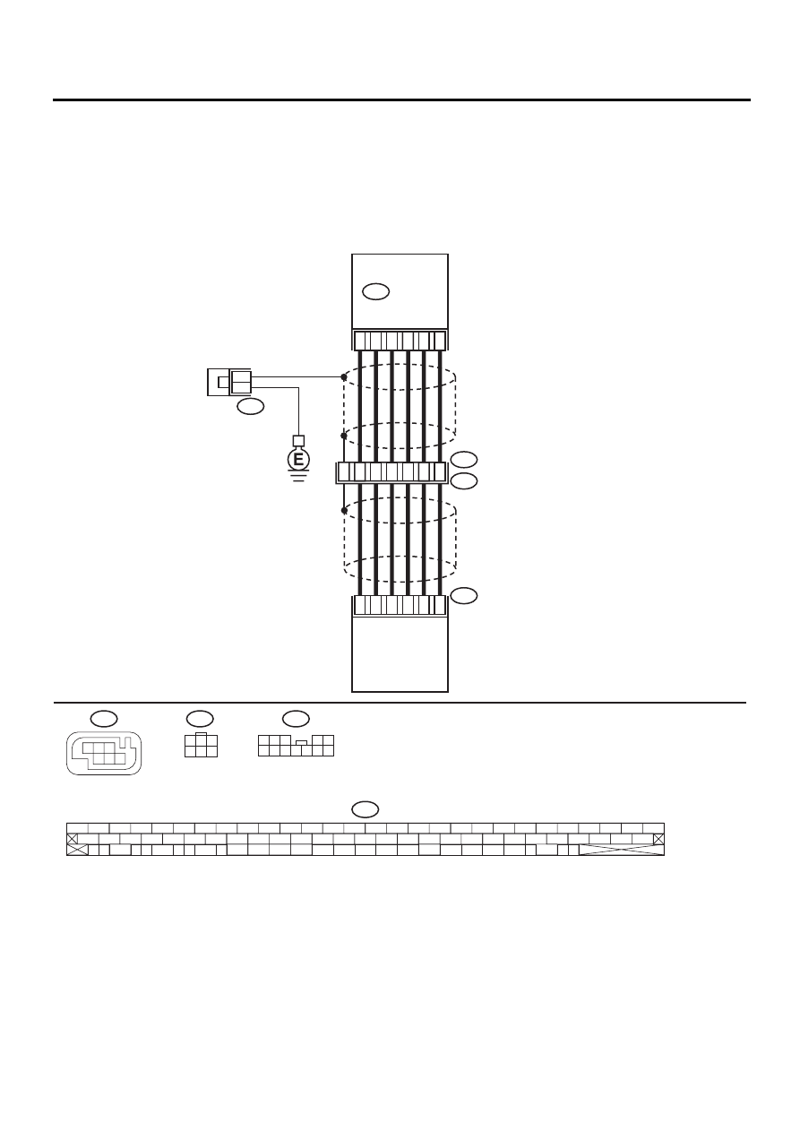
AM:DTC 72 ABNORMAL YAW RATE SENSOR
DIAGNOSIS:
• Faulty yaw rate sensor
TROUBLE SYMPTOM:
• ABS does not operate.
• VDC does not operate.
WIRING DIAGRAM:
VDC00182
65
63
67
66
70
64
10
11
9
F88
F55
R49
4
3
12
2
4
5
8
1
5
6
R100
6
F88
R100
F55
F87
56 57
59 60
62 63
65
82 83
80
27
28
25
26
23
24
21
22
19
20
17
18
15
16
13
14
11
12
9
10
7
8
5
6
3
4
1
2
54
55
52
53
50
51
81
48
49
46
47
44
45
78
79
76
77
75
42
43
40
41
74
72
73
70
71
39
37
38
35
36
69
67
68
66
33
34
61
64
31
32
29
30
58
F87
VDC
CONTROL
MODULE
YAW RATE
AND LATERAL G
SENSOR
1
3
4 5 6
2
1 2 3
4 5
6 7 8 9 10 11 12
3
1
3
4 5 6
2

VDC-119
VDC (DIAGNOSTICS)
DIAGNOSTICS CHART WITH DIAGNOSIS CONNECTOR
Step
Value
Yes
No
1
CHECK THE STEERING WHEEL.
1) Drive the vehicle on a flat road.
2) Stop the vehicle in a straight line.
3) Check the angle of steering wheel.
Is the measured value less than the speci-
fied value?
5
°
Perform centering
alignment of steer-
ing.
2
CHECK RUNNING FIELD.
Was the vehicle driven on banked road sur-
faces or sandy surfaces (not dirt road sur-
faces) or surfaces with holes or bumps at high
speeds?
Driven
Driving on banked
road surfaces or
sandy surfaces
(not dirt road sur-
faces) or surfaces
with holes or
bumps at high
speeds, some-
times results in a
VDCCM memory
trouble code.
3
CHECK INSTALLATION OF YAW RATE AND
LATERAL G SENSOR.
Check installation of yaw rate and lateral G
sensor.
Is the yaw rate and lateral G sensor fixed
securely?
Fixed securely.
Install yaw rate
and lateral G sen-
sor securely.
4
CHECK POWER SUPPLY OF YAW RATE
AND LATERAL G SENSOR.
1) Turn ignition switch OFF.
2) Disconnect connector from yaw rate and
lateral G sensor.
3) Turn ignition switch to ON.
4) Measure voltage between yaw rate and lat-
eral G sensor and chassis ground.
Connector & terminal
(R100) No. 3 (
++++
) — Chassis ground (
−−−−
):
Is the measured value within the specified
range?
10 — 15 V
5
CHECK OUTPUT VOLTAGE OF VDCCM.
1) Turn ignition switch to OFF.
2) Disconnect connector from VDCCM.
3) Remove cover for VDCCM connector.
<Ref. to VDC-19, REMOVE, VDCCM Con-
nector Cover.>
4) Connect connector to VDCCM.
5) Turn ignition switch to ON.
6) Measure voltage between VDCCM connec-
tor and chassis ground.
Connector & terminal
(F87) No. 63 (
++++
) — Chassis ground (
−−−−
):
Is the measured value within the specified
range?
10 — 15 V
Repair harness
between yaw rate
and lateral G sen-
sor and VDCCM.
6
CHECK POOR CONTACT IN CONNECTORS.
Is there poor contact in yaw rate and lateral G
sensor connector?
There is poor contact.
Repair or replace
VDCCM connec-
tor.
Replace VDCCM.
<Ref. to VDC-8,
VDC Control Mod-
ule (VDCCM).>
Нет комментариевНе стесняйтесь поделиться с нами вашим ценным мнением.
Текст