Subaru Legacy III (2000-2003 year). Service manual — part 771
VDC-120
VDC (DIAGNOSTICS)
DIAGNOSTICS CHART WITH DIAGNOSIS CONNECTOR
7
CHECK GROUND CIRCUIT OF YAW RATE
AND LATERAL G SENSOR.
Measure resistance between yaw rate and lat-
eral G sensor and chassis ground.
Connector & terminal
(R100) No. 6 — Chassis ground:
Is the measured value less than the specified
value?
0.5
Ω
8
CHECK GROUND CIRCUIT OF VDCCM.
1) Disconnect connector from VDCCM.
2) Remove cover from VDCCM connector.
<Ref. to VDC-19, REMOVE, VDCCM Con-
nector Cover.>
3) Connect connector to VDCCM.
4) Measure resistance between VDCCM con-
nector and chassis ground.
Connector & terminal
(F87) No. 64 — Chassis ground:
Is the measured value less than the speci-
fied value?
0.5
Ω
Repair harness
between yaw rate
and lateral G sen-
sor and VDCCM.
9
CHECK POOR CONTACT IN CONNECTORS.
Is there poor contact in VDCCM connector?
There is poor contact.
Repair or replace
VDCCM connec-
tor.
Replace VDCCM.
<Ref. to VDC-8,
VDC Control Mod-
ule (VDCCM).>
10
CHECK HARNESS OF YAW RATE AND LAT-
ERAL G SENSOR.
1) Disconnect connector from VDCCM.
2) Measure resistance between VDCCM and
yaw rate and lateral G sensor.
Connector & terminal
(F87) No. 65 — (R100) No. 4:
(F87) No. 66 — (R100) No. 1:
(F87) No. 67 — (R100) No. 2:
Is the measured value less than the speci-
fied value?
0.5
Ω
Repair harness
between yaw rate
and lateral G sen-
sor and VDCCM.
11
CHECK GROUND SHORT OF HARNESS.
Measure resistance between VDCCM connec-
tor and chassis ground.
Connector & terminal
(F87) No. 65 — Chassis ground:
(F87) No. 66 — Chassis ground:
(F87) No. 67 — Chassis ground:
Does the measured value exceed the specified
value?
1 M
Ω
Repair harness
between yaw rate
and lateral G sen-
sor and VDCCM.
12
CHECK BATTERY SHORT OF HARNESS.
Measure voltage between VDCCM connector
and chassis ground.
Connector & terminal
(F87) No. 65 (+) — Chassis ground (
−−−−
):
(F87) No. 66 (+) — Chassis ground (
−−−−
):
(F87) No. 67 (+) — Chassis ground (
−−−−
):
Is the measured value less than the specified
value?
0.5 V
Repair harness
between yaw rate
and lateral G sen-
sor and VDCCM.
Step
Value
Yes
No
VDC-121
VDC (DIAGNOSTICS)
DIAGNOSTICS CHART WITH DIAGNOSIS CONNECTOR
13
CHECK BATTERY SHORT OF HARNESS.
1) Turn ignition switch to ON.
2) Measure voltage between VDCCM and
chassis ground.
Connector & terminal
(F87) No. 65 (+) — Chassis ground (
−−−−
):
(F87) No. 66 (+) — Chassis ground (
−−−−
):
(F87) No. 67 (+) — Chassis ground (
−−−−
):
Is the measured value less than the speci-
fied value?
0.5 V
Repair harness
between yaw rate
and lateral G sen-
sor and VDCCM.
14
CHECK YAW RATE AND LATERAL G SEN-
SOR.
1) Turn ignition switch to OFF.
2) Install yaw rate and lateral G sensor to
body.
3) Connect all connectors.
4) Turn ignition switch to ON.
5) Measure voltage between VDCCM connec-
tor terminals.
Connector & terminal
(F87) No. 66 (+) — No. 64 (
−−−−
):
Is the measured value within the specified
range?
2.1 — 2.9 V
Replace yaw rate
and lateral G sen-
sor. <Ref. to VDC-
22, Yaw Rate and
Lateral G Sensor.>
15
CHECK YAW RATE AND LATERAL G SEN-
SOR.
1) Turn ignition switch to ON.
2) Check oscilloscope signal pattern between
VDCCM connector terminals.<Ref. to VDC-
17, WAVEFORM, MEASUREMENT, Con-
trol Module I/O Signal.>
Connector & terminal
(F87) No. 67 (+) — No. 64 (
−−−−
):
Is the oscilloscope pattern the same as
shown in the figure?
Same pattern.
Replace VDCCM.
<Ref. to VDC-8,
VDC Control Mod-
ule (VDCCM).>
16
CHECK YAW RATE SENSOR.
Check oscilloscope pattern between yaw rate
and lateral G sensor terminals.<Ref. to VDC-
17, WAVEFORM, MEASUREMENT, Control
Module I/O Signal.>
Connector & terminal
(F87) No. 65 (+) — No. 64 (
−−−−
):
Is the oscilloscope pattern the same as shown
in the figure?
Same pattern.
Replace VDCCM.
<Ref. to VDC-8,
VDC Control Mod-
ule (VDCCM).>
Replace yaw rate
and lateral G sen-
sor. <Ref. to VDC-
8, VDC Control
Module
(VDCCM).>
Step
Value
Yes
No
VDC-122
VDC (DIAGNOSTICS)
DIAGNOSTICS CHART WITH DIAGNOSIS CONNECTOR
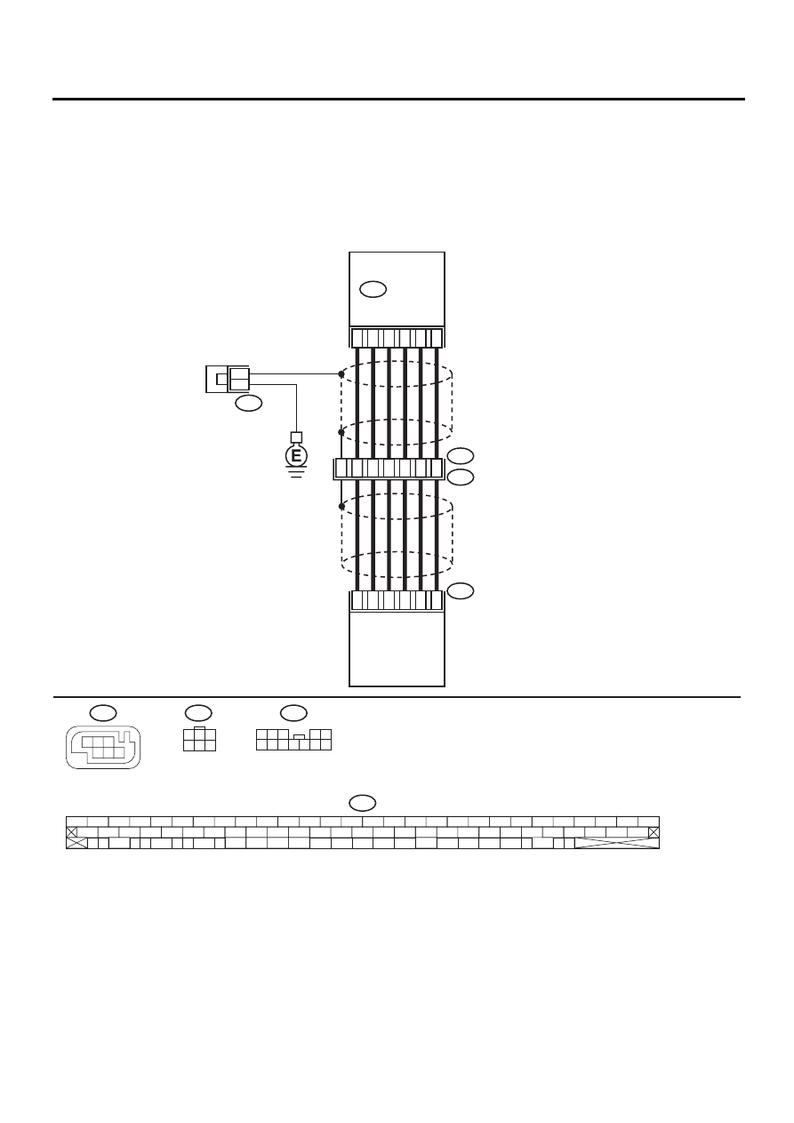
AN:DTC 73 ABNORMAL LATERAL G SENSOR
DIAGNOSIS:
• Faulty lateral G sensor
TROUBLE SYMPTOM:
• ABS does not operate.
• VDC does not operate.
WIRING DIAGRAM:
VDC00182
65
63
67
66
70
64
10
11
9
F88
F55
R49
4
3
12
2
4
5
8
1
5
6
R100
6
F88
R100
F55
F87
56 57
59 60
62 63
65
82 83
80
27
28
25
26
23
24
21
22
19
20
17
18
15
16
13
14
11
12
9
10
7
8
5
6
3
4
1
2
54
55
52
53
50
51
81
48
49
46
47
44
45
78
79
76
77
75
42
43
40
41
74
72
73
70
71
39
37
38
35
36
69
67
68
66
33
34
61
64
31
32
29
30
58
F87
VDC
CONTROL
MODULE
YAW RATE
AND LATERAL G
SENSOR
1
3
4 5 6
2
1 2 3
4 5
6 7 8 9 10 11 12
3
1
3
4 5 6
2
VDC-123
VDC (DIAGNOSTICS)
DIAGNOSTICS CHART WITH DIAGNOSIS CONNECTOR
Step
Value
Yes
No
1
CHECK INSTALLATION OF LATERAL G
SENSOR.
Check installation of lateral G sensor.
Is the yaw rate and lateral G sensor fixed
securely?
Fixed securely.
Install yaw rate
and lateral G sen-
sor securely.
2
CHECK INPUT VOLTAGE OF G SENSOR.
1) Turn ignition switch to OFF.
2) Remove console box.
3) Disconnect connector from yaw rate and
lateral G sensor.
4) Turn ignition switch to ON.
5) Measure voltage between yaw rate and lat-
eral G sensor connector terminals.
Connector & terminal
(R100) No. 3 (+) — No. 6 (
−−−−
):
Is the measured value within the specified
range?
10 — 15 V
Repair harness/
connector
between yaw rate
and lateral G sen-
sor and VDCCM.
3
CHECK YAW RATE AND LATERAL G SEN-
SOR.
1) Turn ignition switch to OFF.
2) Measure resistance between yaw rate and
lateral G sensor terminals.
Terminals
No. 3 — No. 5:
Is the measured value within the specified
range?
4.3 — 4.9 k
Ω
Replace yaw rate
and lateral G sen-
sor. <Ref. to VDC-
22, Yaw Rate and
Lateral G Sensor.>
4
CHECK OPEN CIRCUIT IN YAW RATE AND
LATERAL G SENSOR OUTPUT HARNESS
AND GROUND HARNESS.
1) Connect connector to yaw rate and lateral
G sensor.
2) Disconnect connector from VDCCM.
3) Measure resistance between VDCCM con-
nector terminals.
Connector & terminal
(F87) No. 63 — No. 70:
Is the measured value within the specified
range?
4.3 — 4.9 k
Ω
Repair harness/
connector
between yaw rate
and lateral G sen-
sor and VDCCM.
5
CHECK GROUND SHORT IN YAW RATE
AND LATERAL G SENSOR HARNESS.
1) Disconnect connector from yaw rate and
lateral G sensor.
2) Measure resistance between VDCCM con-
nector and chassis ground.
Connector & terminal
(F87) No. 63 — Chassis ground:
(F87) No. 70 — Chassis ground:
(F87) No. 64 — Chassis ground:
Does the measured value exceed the spec-
ified value?
1 M
Ω
Repair harness
between yaw rate
and lateral G sen-
sor and VDCCM.
6
CHECK BATTERY SHORT OF HARNESS.
Measure voltage between VDCCM connector
and chassis ground.
Connector & terminal
(F87) No. 63 (+) — Chassis ground (
−−−−
):
(F87) No. 70 (+) — Chassis ground (
−−−−
):
(F87) No. 64 (+) — Chassis ground (
−−−−
):
Is the measured value less than the specified
value?
1 V
Repair harness
between yaw rate
and lateral G sen-
sor and VDCCM.
Нет комментариевНе стесняйтесь поделиться с нами вашим ценным мнением.
Текст