Subaru Legacy III (2000-2003 year). Service manual — part 768
VDC-108
VDC (DIAGNOSTICS)
DIAGNOSTICS CHART WITH DIAGNOSIS CONNECTOR
AK:DTC 52 ABNORMAL MOTOR AND/OR MOTOR RELAY
DIAGNOSIS:
• Faulty motor
• Faulty motor relay
• Faulty harness connector
TROUBLE SYMPTOM:
• ABS does not operate.
• VDC does not operate.
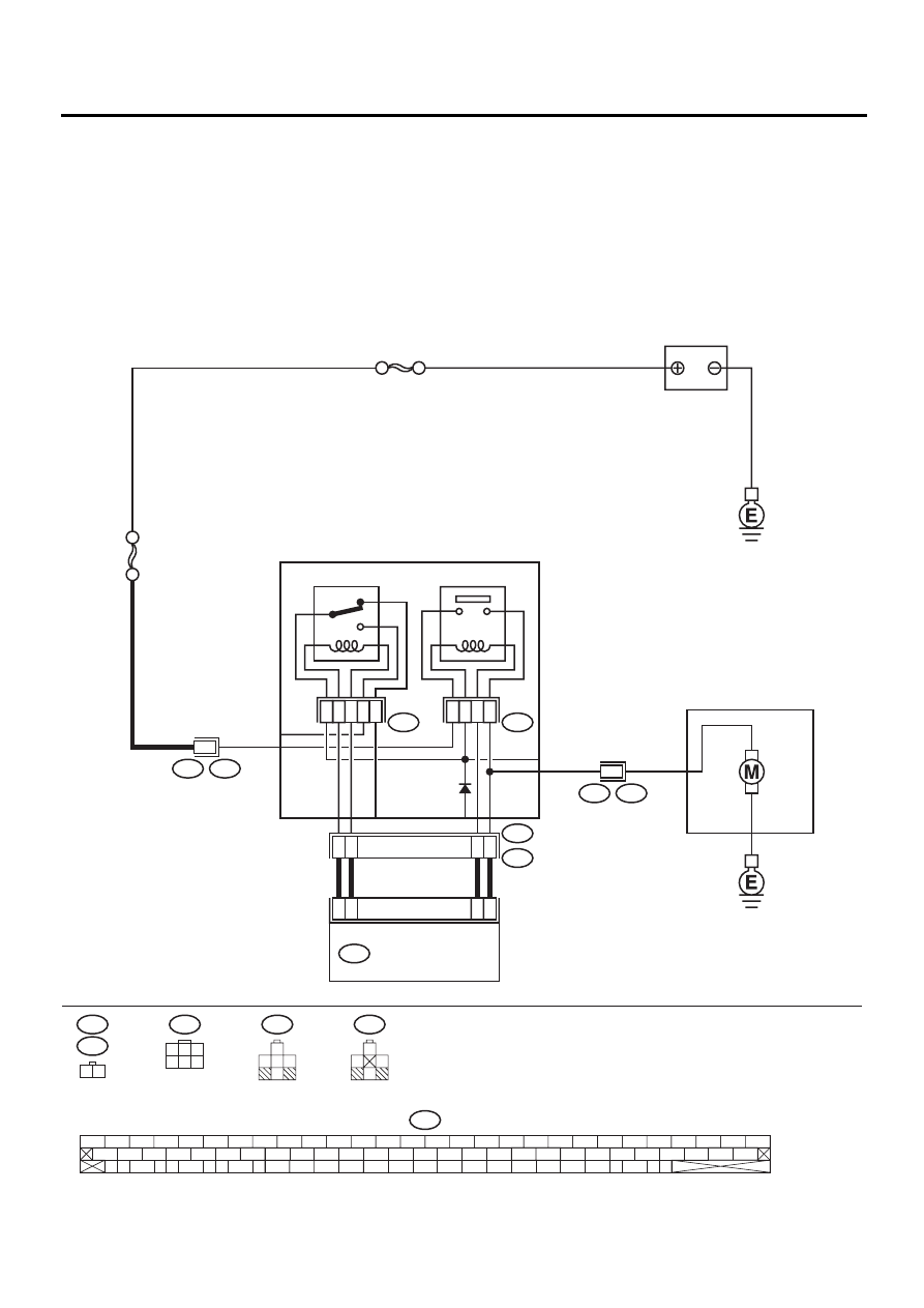
WIRING DIAGRAM:
VDC00155
VDC HYDRAULIC UNIT
87
87a
VDC2
VDC1
4
6
86
1
85
30
30
86
85
87
5
VDC4
F90
F87
56 57
59 60
62 63
65
82 83
80
27
28
25
26
23
24
21
22
19
20
17
18
15
16
13
14
11
12
9
10
7
8
5
6
3
4
1
2
54
55
52
53
50
51
81
48
49
46
47
44
45
78
79
76
77
75
42
43
40
41
74
72
73
70
71
39
37
38
35
36
69
67
68
66
33
34
61
64
31
32
29
30
58
SBF HOLDER 50A
VDC7
VDC6
MOTOR RELAY
VALVE RELAY
VDC CONTROL MODULE
22
10
27
47
F87
1
VDC3
F89
2
SBF-1 100A
RELAY BOX
F89
VDC1
1 2
F90
VDC6
1
3
4 5 6
2
85
86
87
30
85 87a 86
87
30
VDC7
BATTERY

VDC-109
VDC (DIAGNOSTICS)
DIAGNOSTICS CHART WITH DIAGNOSIS CONNECTOR
Step
Value
Yes
No
1
CHECK RESISTANCE OF MOTOR RELAY.
1) Turn ignition switch to OFF.
2) Remove motor relay from relay box.
3) Measure resistance between motor relay
terminals.
Terminals
No. 85 — No. 86:
Is the measured value within the specified
range?
70 — 90
Ω
Replace motor
relay.
2
CHECK CONTACT POINT OF MOTOR RE-
LAY.
1) Connect battery to motor relay terminals
No. 85 and No. 86.
2) Measure resistance between motor relay
terminals.
Terminals
No. 30 — No. 87:
Is the measured value less than the speci-
fied value?
0.5
Ω
Replace motor
relay.
3
CHECK CONTACT POINT OF MOTOR RE-
LAY.
1) Disconnect battery from motor relay termi-
nals.
2) Measure resistance between motor relay
terminals.
Terminals
No. 30 — No. 87:
Does the measured value exceed the spec-
ified value?
1 M
Ω
Replace motor
relay.
4
CHECK SHORT OF MOTOR RELAY.
Measure resistance between motor relay ter-
minals.
Terminals
No. 85 — No. 30:
No. 85 — No. 87:
Does the measured value exceed the specified
value?
1 M
Ω
Replace motor
relay.
5
CHECK INPUT VOLTAGE OF RELAY BOX.
1) Disconnect connector (F89) from relay box.
2) Disconnect connector from VDCCM.
3) Measure voltage between relay box con-
nector and chassis ground.
Connector & terminal
(F89) No. 2 (+) — Chassis ground (
−−−−
):
Is the measured value within the specified
range?
10 — 15 V
Repair harness/
connector
between battery
and relay box, and
check fuse SBF
holder.
6
CHECK INPUT VOLTAGE OF MOTOR RE-
LAY.
1) Connect connector (F89) to relay box.
2) Measure voltage between relay box and
chassis ground.
Connector & terminal
(VDC7) No. 87 (+) — Chassis ground (
−−−−
):
Is the measured value within the specified
range?
10 — 15 V
Replace relay box.

VDC-110
VDC (DIAGNOSTICS)
DIAGNOSTICS CHART WITH DIAGNOSIS CONNECTOR
7
CHECK OPEN CIRCUIT IN CONTACT POINT
CIRCUIT OF RELAY BOX.
1) Turn ignition switch to OFF.
2) Disconnect connectors (VDC2, F90) from
relay box.
3) Measure resistance between relay box con-
nector unit and motor relay installing por-
tion.
Connector & terminal
(VDC1) No. 1 — (VDC7) No. 30:
Is the measured value less than the speci-
fied value?
0.5
Ω
Replace relay box.
8
CHECK OPEN CIRCUIT IN MONITOR SYS-
TEM CIRCUIT OF RELAY BOX.
Measure resistance between relay box con-
nector and motor relay installing point.
Connector & terminal
(VDC4) No. 6 — (VDC7) No. 30:
Is the measured value less than the specified
value?
0.5
Ω
Replace relay box.
9
CHECK OPEN CIRCUIT IN CONTROL CIR-
CUIT OF RELAY BOX.
Measure resistance between motor relay
installing point and relay box connector.
Connector & terminal
(VDC4) No. 4 — (VDC7) No. 86:
Is the measured value less than the specified
value?
0.5
Ω
Replace relay box.
10
CHECK OPEN CIRCUIT IN CONTROL CIR-
CUIT OF RELAY BOX.
1) Remove valve relay from relay box.
2) Measure resistance between motor relay
installing point and valve relay installing
point.
Connector & terminal
(VDC7) No. 85 — (VDC6) No. 30:
Is the measured value less than the speci-
fied value?
0.5
Ω
Replace relay box.
11
CHECK GROUND SHORT IN CIRCUIT OF
RELAY BOX.
Measure resistance between relay box con-
nector unit and chassis ground.
Connector & terminal
(VDC4) No. 4 — Chassis ground:
(VDC4) No. 6 — Chassis ground:
Does the measured value exceed the specified
value?
1 M
Ω
Replace relay box.
12
CHECK BATTERY SHORT IN CIRCUIT OF
RELAY BOX.
Measure voltage between relay box connector
and chassis ground.
Connector & terminal
(VDC4) No. 4 (+) — Chassis ground (
−−−−
):
(VDC4) No. 6 (+) — Chassis ground (
−−−−
):
Is the measured value less than the specified
value?
1 V
Replace relay box.
Step
Value
Yes
No

VDC-111
VDC (DIAGNOSTICS)
DIAGNOSTICS CHART WITH DIAGNOSIS CONNECTOR
13
CHECK BATTERY SHORT IN CIRCUIT OF
RELAY BOX.
1) Turn ignition switch to ON.
2) Measure voltage between relay box con-
nector and chassis ground.
Connector & terminal
(VDC4) No. 4 (+) — Chassis ground (
−−−−
):
(VDC4) No. 6 (+) — Chassis ground (
−−−−
):
Is the measured value less than the speci-
fied value?
1 V
Replace relay box.
14
CHECK OPEN CIRCUIT IN RELAY CON-
TROL SYSTEM HARNESS.
1) Turn ignition switch to OFF.
2) Measure resistance between VDCCM con-
nector and relay box connector.
Connector & terminal
(F87) No. 22 — (F90) No. 4:
(F87) No. 10 — (F90) No. 6:
Is the measured value less than the speci-
fied value?
0.5
Ω
Repair harness
connector
between VDCCM
and relay box.
15
CHECK GROUND SHORT IN HARNESS BE-
TWEEN RELAY BOX AND VDCCM.
Measure resistance between VDCCM connec-
tor and chassis ground.
Connector & terminal
(F87) No. 22 — Chassis ground:
(F87) No. 10 — Chassis ground:
Does the measured value exceed the specified
value?
1 M
Ω
Repair harness
between VDCCM
and relay box.
Check fuse SBF
holder.
16
CHECK BATTERY SHORT IN HARNESS BE-
TWEEN RELAY BOX AND VDCCM.
Measure voltage between VDCCM connector
and chassis ground.
Connector & terminal
(F87) No. 22 (+) — Chassis ground (
−−−−
):
(F87) No. 10 (+) — Chassis ground (
−−−−
):
Is the measured value less than the specified
value?
1 V
Repair harness
between VDCCM
and relay box.
Check fuse SBF
holder.
17
CHECK BATTERY SHORT IN HARNESS BE-
TWEEN RELAY BOX AND VDCCM.
1) Turn ignition switch to ON.
2) Measure voltage between VDCCM connec-
tor and chassis ground.
Connector & terminal
(F87) No. 22 (+) — Chassis ground (
−−−−
):
(F87) No. 10 (+) — Chassis ground (
−−−−
):
Is the measured value less than the speci-
fied value?
1 V
Repair harness
between VDCCM
and relay box.
Check fuse SBF
holder.
18
CHECK CONDITION OF MOTOR GROUND.
Tightening torque:
33
±±±±
10 N·m (3.3
±±±±
1.0 kgf-m, 24
±±±±
7 ft-lb)
Is the motor ground terminal tightly clamped?
Clamped securely.
Tighten the clamp
of motor ground
terminal.
Step
Value
Yes
No
Нет комментариевНе стесняйтесь поделиться с нами вашим ценным мнением.
Текст