Subaru Legacy III (2000-2003 year). Service manual — part 308
EN(H6DO)-34
ENGINE (DIAGNOSTICS)
SUBARU SELECT MONITOR
10.Subaru Select Monitor
A: OPERATION
1. HOW TO USE SUBARU SELECT MONI-
TOR
1) Prepare Subaru Select Monitor kit. <Ref. to
EN(H6DO)-9, PREPARATION TOOL, General De-
scription.>
2) Connect diagnosis cable to Subaru Select Mon-
itor.
3) Insert cartridge into Subaru Select Monitor.
<Ref. to EN(H6DO)-9, PREPARATION TOOL,
General Description.>
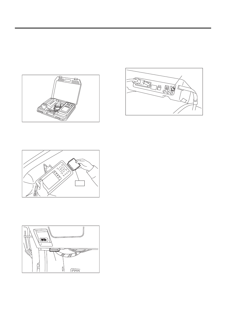
4) Connect Subaru Select Monitor to data link con-
nector.
(1) Data link connector located in the lower por-
tion of the instrument panel (on the driver's
side).
(2) Connect diagnosis cable to data link con-
nector.
CAUTION:
Do not connect scan tools except for Subaru
Select Monitor and OBD-II general scan tool.
5) Turn ignition switch to ON (engine OFF) and
Subaru Select Monitor switch to ON.
6) Using Subaru Select Monitor, call up diagnostic
trouble code(s) and various data, then record them.
2. READ DIAGNOSTIC TROUBLE CODE
(DTC) FOR ENGINE. (NORMAL MODE)
Refer to Read Diagnostic Trouble Code for infor-
mation about how to indicate DTC. <Ref. to
EN(H6DO)-46, Read Diagnostic Trouble Code.>
3. READ DIAGNOSTIC TROUBLE CODE
(DTC) FOR ENGINE. (OBD MODE)
Refer to Read Diagnostic Trouble Code for infor-
mation about how to indicate DTC. <Ref. to
EN(H6DO)-46, Read Diagnostic Trouble Code.>
(A) Data link connector
EN-00038
ST
EN-00039
EN-00710
( A )
(A) Power switch
EN-00040
( A )

EN(H6DO)-35
ENGINE (DIAGNOSTICS)
SUBARU SELECT MONITOR
4. READ CURRENT DATA FOR ENGINE. (NORMAL MODE)
1) On the «Main Menu» display screen, select the {Each System Check} and press the [YES] key.
2) On the «System Selection Menu» display screen, select the {Engine Control System} and press the [YES]
key.
3) Press the [YES] key after displayed the information of engine type.
4) On the «Engine Diagnosis» display screen, select the {Current Data Display & Save} and press the [YES]
key.
5) On the «Data Display Menu» display screen, select the {Data Display} and press the [YES] key.
6) Using the scroll key, move the display screen up or down until the desired data is shown.
• A list of the support data is shown in the following table.
Contents
Display
Unit of measure
Battery voltage
Battery Voltage
V
Vehicle speed signal
Vehicle Speed
km/h or MPH
Engine speed signal
Engine Speed
rpm
Engine coolant temperature signal
Coolant Temp.
°
C or
°
F
Ignition timing signal
Ignition Timing
deg
Throttle position signal
Throttle Opening Angle
%
Throttle position signal
Throttle Sensor Voltage
V
Injection pulse width 1
Fuel Injection #1 Pulse
ms
Injection pulse width 2
Fuel Injection #2 Pulse
ms
Idle air control signal
ISC Valve Duty Ratio
%
Engine load data
Engine Load
%
Front oxygen (A/F) sensor output signal 1
A/F Sensor #1
—
Front oxygen (A/F) sensor output signal 2
A/F Sensor #2
—
Front oxygen (A/F) sensor resistance 1
A/F Sensor #1 Resistance
Ω
Front oxygen (A/F) sensor resistance 2
A/F Sensor #2 Resistance
Ω
Rear oxygen sensor output signal
Rear O2 Sensor
V
Short term fuel trim 1
A/F Correction #1
%
Short term fuel trim 2
A/F Correction #2
%
Knock sensor signal
Knocking Correction
deg
Atmospheric absolute pressure signal
Atmosphere Pressure
mmHg or kPa or inHg or
psig
Intake manifold relative pressure signal
Mani. Relative Pressure
mmHg or kPa or inHg or
psig
EGR control signal
No. of EGR Steps
STEP
Front oxygen (A/F) sensor 1 current
A/F Sensor #1 Current
mA
Front oxygen (A/F) sensor 2 current
A/F Sensor #2 Current
mA
Intake manifold absolute pressure signal
Mani. Absolute Pressure
mmHg or kPa or inHg or
psig
A/F correction (short term fuel trim) by rear oxygen sensor
A/F Correction #3
%
Long term whole fuel trim 1
A/F Learning #1
%
Long term whole fuel trim 2
A/F Learning #2
%
Long term whole fuel trim 3
A/F Learning #3
%
Front oxygen (A/F) sensor heater current 1
A/F Heater Current 1
A
Front oxygen (A/F) sensor heater current 2
A/F Heater Current 2
A
Rear oxygen sensor heater voltage
Rear O2 Heater Voltage
V
Canister purge control solenoid valve duty ratio
CPC Valve Duty Ratio
%
Fuel level signal
Fuel Level
V
Intake air temperature signal
Intake Air Temp.
°
C or
°
F
Ignition switch signal
Ignition Switch
ON or OFF
Alternator output signal
Alternator Control Output
%
Fuel pump controller control duty ratio
FPC Duty Ratio
%
Test mode connector signal
Test Mode Signal
ON or OFF

EN(H6DO)-36
ENGINE (DIAGNOSTICS)
SUBARU SELECT MONITOR
NOTE:
• For detailed operation procedure, refer to the SUBARU SELECT MONITOR OPERATION MANUAL.
• For select monitor display details, refer to the following.
Engine Load
Display: 0 — 100%
The engine load is displayed. The ECM calculates
the engine load via the engine speed and signals
from the pressure sensor. The engine load increas-
es when the engine speed and absolute pressure
of the intake manifold increase.
Coolant Temp.
Display:
−−−−
40 to 215
°°°°
C (
−−−−
40 to 419
°°°°
F)
The coolant temperature transmitted from the en-
gine coolant temperature sensor is displayed.
ATF Correction #1, #2 and #3
Display:
−−−−
100 to 99%
Using the signal from the front oxygen (A/F) sen-
sor, the correction value of the fuel supply amount
regulated by the ECM is indicated. When the A/F is
lean and when displayed value becomes 0 % or
more, ECM increases the fuel. When the A/F is rich
and when displayed value becomes 0 % or less,
ECM decreases the fuel.
A/F Learning #1, #2 and #3
Display:
−−−−
100 to 99.2%
The ECM calculates the long-term fuel trim value
from the short-term fuel trim value. The long-term
fuel trim value means the correction value of long-
term fuel supply amount. If the displayed value is
less than 0 %, the fuel system is in rich status and
the ECM restricts the fuel supply (by shortening the
injector pulse). If the displayed value is more than 0
%, the fuel system is in lean status and the ECM in-
creases the fuel supply (by extending the injector
pulse).
Mani Absolute Pressure
Display: 0 — 254.9 kPa (0 — 1,912.5 mmHg,
0 — 75.3 inHg)
The pressure in the intake manifold is displayed.
The ECM detects the pressure in the intake tube
via the signal from the pressure sensor. The ECM
calculates the air mass required for the engine.
Engine Speed
Display: 0 — 16,383 rpm
The engine speed transmitted from the crankshaft
position sensor is detected.
Neutral position switch signal
Neutral Position Switch
ON or OFF
Air conditioner switch signal
A/C Switch
ON or OFF
Radiator fan relay signal 1
Radiator Fan Relay #1
ON or OFF
Fuel pump relay signal
Fuel Pump Relay
ON or OFF
Knocking signal
Knocking Signal
ON or OFF
Radiator fan relay signal 2
Radiator Fan Relay #2
ON or OFF
Engine torque control signal #1
Torque Control Signal #1
ON or OFF
Engine torque control signal #2
Torque Control Signal #2
ON or OFF
Engine torque control permission signal
Torque Control Permission Sig-
nal
ON or OFF
Starter switch signal
Starter Switch
ON or OFF
Idle switch signal
Idle Switch Signal
ON or OFF
Crankshaft position sensor signal
Crankshaft Position Sig.
ON or OFF
Camshaft position sensor signal
Camshaft Position Sig.
ON or OFF
Rear defogger switch signal
Rear Defogger SW
ON or OFF
Blower fan switch signal
Blower Fan SW
ON or OFF
Small light switch signal
Light Switch
ON or OFF
Power steering switch signal
P/S Switch
ON or OFF
Air conditioner lock switch signal
A/C Lock Signal
ON or OFF
Air conditioner mid pressure switch signal
A/C Mid Pressure Switch
ON or OFF
Air conditioner compressor signal
A/C Compressor Signal
ON or OFF
Radiator fan relay signal 3
Radiator Fan Relay #3
ON or OFF
Induction control solenoid signal
Variable Intake Air Sol.
ON or OFF
Rear oxygen sensor rich signal
Rear O2 Rich Signal
ON or OFF
Electric load signal (Wiper switch signal)
Electric load signal
ON or OFF
Contents
Display
Unit of measure
EN(H6DO)-37
ENGINE (DIAGNOSTICS)
SUBARU SELECT MONITOR
Vehicle Speed
Display: 0 — 255 km/h (0 — 158 MPH)
The vehicle speed transmitted from the vehicle
speed sensor is displayed.
Ignition Timing
Display:
−−−−
64 to 63.5 deg.
The advanced ignition timing value is displayed.
The ECM calculates the advanced ignition timing
value using engine coolant temperature, engine
speed, and engine load.
Intake Air Temp.
Display: 40 — 215
°°°°
C (104 — 419
°°°°
F)
The intake air temperature is displayed. The ECM
detects the intake air temperature via the signal
from the intake air temperature sensor, and cor-
rects the ignition timing and fuel supply amount.
Rear O2 Sensor
Display: 0 — 327.7 Volt
The ECM corrects air-fuel ratio by the signal sent
from O2 sensor. Also, the signal is used for catalyst
degradation diagnosis.
Battery Voltage
Display: 0 — 20.4 V
The battery voltage is displayed.
Throttle Sensor Voltage
Display: 0 — 5 V
The throttle angle is displayed in voltage. When the
throttle is fully-closed, the displayed voltage value
is approx. 0.5 V. When it is fully-open, the voltage is
approx. 4 V or more.
Fuel Injection #1 and #2 Pulse
Display: 0 — 65.3 msec (0 — 214.2 ft/sec)
The injector valve opening time is displayed. The
longer the injector valve opening time, the more the
fuel is supplied. The higher the engine load, the
longer the injector valve opening time becomes.
Knocking Correction
Display:
−−−−
64 to 63.5 deg.
The ECM controls the ignition timing via the signal
from the knock sensor.
Atmosphere Pressure
Display: 0 — 254.9 kPa (0 — 1,912.5 mmHg,
0 — 75.3 inHg)
The atmospheric pressure is displayed. The ECM
detects the atmospheric pressure via the signal
from the atmosphere sensor.
Mani. Relative Pressure
Display:
−−−−
128 — 128 kPa (
−−−−
952 — 952 mm-
Hg,
−−−−
37.5 — 37.5 inHg)
A value calculated by subtracting the absolute
pressure in the intake tube from the atmospheric
pressure is displayed. A larger load leads to a larg-
er value.
Front O2 Heater #1, #2 Current
Display: 0 — 25.5 A
The heater current of the A/F sensor is displayed. A
larger current value leads to increased heat gener-
ation.
Fuel Level
Display: 0 — 5 V
The float inside the fuel tank is a variable resistor
which varies the resistance based on fuel level.
The ECM then averages this voltage and the signal
voltage from the fuel tank in order to determine fuel
level. The scan tool displays close to 0.7 volts for
an empty tank, and close to 5 volts for a full tank.
CPC Valve Duty Ratio
Display: 0 — 100%
The purge control solenoid valve is regulated by
the ECM. The displayed value of 0 % indicates that
the purge amount is 0, and 100 % indicates that the
purge amount becomes the maximum.
A/F sensor #1, #2
Display: 0 — 2
The air surplus ratio output from the front oxygen
(A/F) sensor is displayed. Air overflow ratio = 1.0 is
regarded as a stoichiometric A/F ratio. A value
above 1.0 indicates A/F lean range, and below 1.0
indicates A/F rich range.
A/F Correction #3
Display:
The correction value of fuel supply amount regulat-
ed by the ECM via the signal from the rear oxygen
sensor is displayed.
A/F Sensor #1, #2 Current
Display:
−−−−
16 — 15.9 mA
A value of 0 mA is regarded as a stoichiometric A/
F ratio. A negative value indicates A/F rich range,
and positive value indicates A/F lean range.
A/F Sensor #1, #2 Resistance
Display: 0 — 255
Ω
Ω
Ω
Ω
The resistance value of the front oxygen (A/F) sen-
sor is displayed. At idle after warm-up, the resis-
tance value shows 27 to 32 ohm.
Нет комментариевНе стесняйтесь поделиться с нами вашим ценным мнением.
Текст