Subaru Legacy III (2000-2003 year). Service manual — part 306

EN(H6DO)-26
ENGINE (DIAGNOSTICS)
ENGINE CONTROL MODULE (ECM) I/O SIGNAL
Self-shutoff control
B134
2
ON: 0.5, or less
OFF: 10 — 13
ON: 0.5, or less
—
Malfunction indicator lamp
B137
15
—
—
Light “ON”: 1, or less
Light “OFF”: 10 — 14
Engine speed output
B136
9
—
0 — 13
Waveform
Torque control 1 signal
B134
19
5
5
—
Torque control 2 signal
B134
18
5
5
—
Torque control cut signal
B136
14
8
8
—
EGR solenoid valve (A
−
)
B137
26
10 — 13
13 — 14
—
EGR solenoid valve (B
−
)
B137
25
10 — 13
13 — 14
—
EGR solenoid valve (A+)
B137
14
10 — 13
13 — 14
—
EGR solenoid valve (B+)
B137
13
10 — 13
13 — 14
—
Induction control solenoid valve
B137
23
0
ON: 0
OFF: 13 — 14
—
Purge control solenoid valve
B137
16
ON: 1, or less
OFF: 10 — 13
ON: 1, or less
OFF: 13 — 14
—
Fuel level sensor
B135
25
0.12 — 4.75
0.12 — 4.75
—
A/C pressure switch
B135
23
OFF: 5
ON: 1, or less
OFF: 5
—
AT diagnosis input signal
B135
20
Less than 1
←→
More
than 4
Less than 1
←→
More
than 4
Waveform
AT load signal
B135
28
4.3 — 4.4
0.9 — 1.4
—
Small light switch
B134
17
ON: 0
OFF: 10 — 13
ON: 0
OFF: 13 — 14
—
Blower fan switch
B134
9
ON: 0
OFF: 10 — 13
ON: 0
OFF: 13 — 14
—
Rear defogger switch
B134
3
ON: 0
OFF: 10 — 13
ON: 0
OFF: 13 — 14
—
Wiper switch
B135
3
ON: 0
OFF: 10 — 13
ON: 0
OFF: 13 — 14
—
Front oxygen (A/F) sensor signal
RH (+)
B137
29
3.7 — 3.9
3.7 — 3.9
—
Front oxygen (A/F) sensor signal
RH (
−
)
B137
19
2.6 — 4.4
3.4 — 3.6
—
Front oxygen (A/F) sensor signal
LH (+)
B137
30
3.7 — 3.9
3.7 — 3.9
—
Front oxygen (A/F) sensor signal
LH (
−
)
B137
20
2.6 — 4.4
3.4 — 3.6
—
Front oxygen (A/F) sensor shield
B137
18
0
0
—
Pressure sensor
B135
8
3.0 — 4.2
1.0 — 2.6
—
Intake air temperature sensor
B135
27
—
—
—
Power steering switch
B135
24
ON: 0
OFF: 5
ON: 0
OFF: 5
—
SSM/GST communication line
B134
21
Less than 1
←→
More
than 4
Less than 1
←→
More
than 4
—
GND (sensors)
B134
15
0
0
—
GND (injectors)
B136
8
0
0
—
GND (ignition system)
B136
18
0
0
—
GND (power supply)
B134
22
0
0
—
B136
17
0
0
—
GND (control systems)
B134
7
0
0
—
15
0
0
—
Content
Con-
nector
No.
Termi-
nal No.
Signal (V)
Note
Ignition SW ON
(Engine OFF)
Engine ON (Idling)

EN(H6DO)-27
ENGINE (DIAGNOSTICS)
ENGINE CONTROL MODULE (ECM) I/O SIGNAL
GND (oxygen sensor
heater LH)
1
B137
21
0
0
—
2
B137
31
GND (oxygen sensor
heater RH)
1
B137
9
0
0
—
2
B137
8
Content
Con-
nector
No.
Termi-
nal No.
Signal (V)
Note
Ignition SW ON
(Engine OFF)
Engine ON (Idling)
EN(H6DO)-28
ENGINE (DIAGNOSTICS)
ENGINE CONTROL MODULE (ECM) I/O SIGNAL
B: MEASUREMENT
Measure input/output signal voltage.
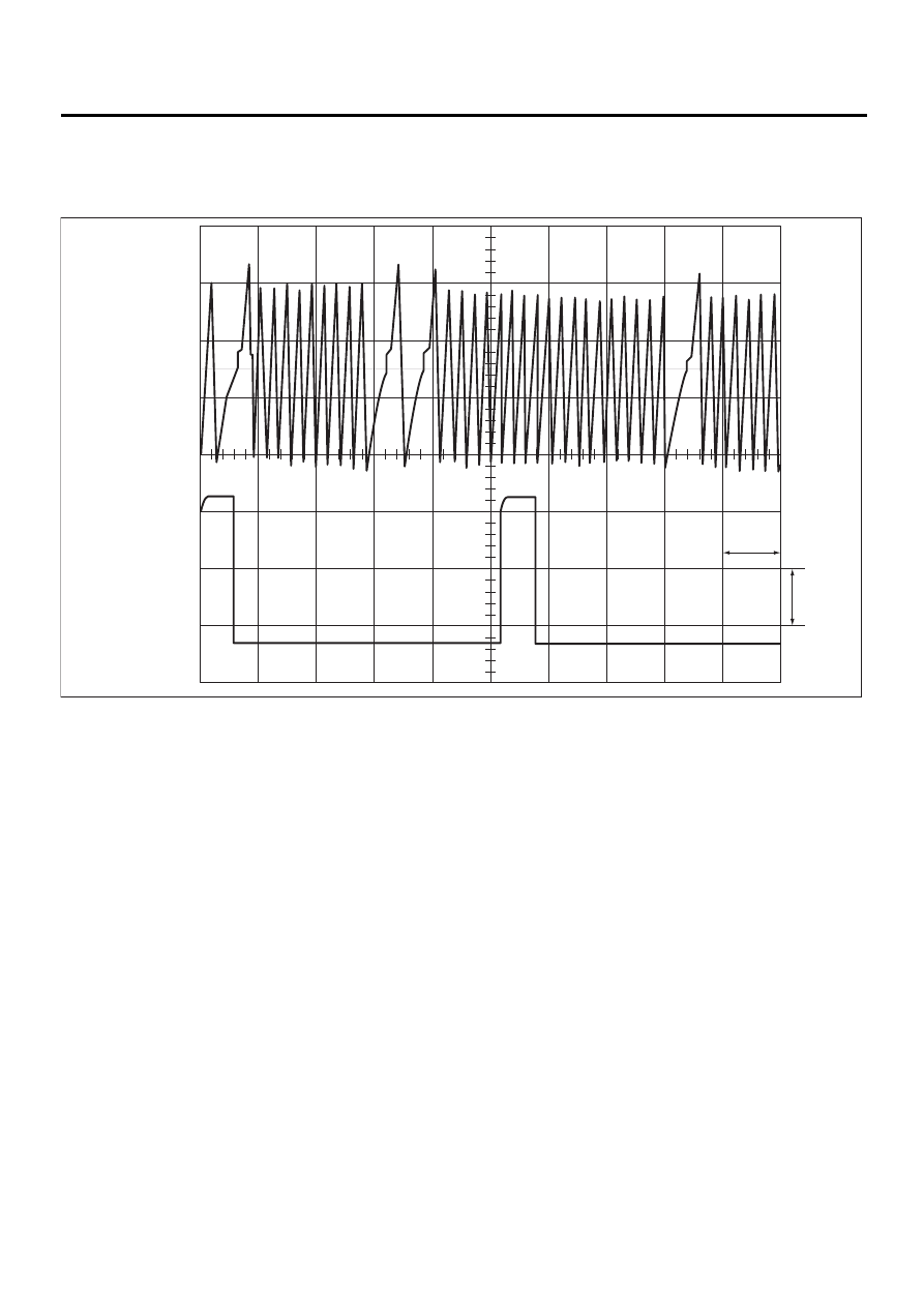
1. WAVEFORM
EN-00799
0V
2V
0V
10 ms
Crankshaft position
sensor
Terminal No. 1-2
Crankshaft position
sensor
Terminal No. 2-3
0V

EN(H6DO)-29
ENGINE (DIAGNOSTICS)
ENGINE CONDITION DATA
6. Engine Condition Data
A: ELECTRICAL SPECIFICATION
Measuring condition:
• After warm-up the engine.
• Gear position is in “N” or “P” position.
• A/C is turned OFF.
• All accessory switches are turned OFF.
Content
Specified data
Engine load
1.6 — 4.0 (%): Idling
6.4 — 12.8 (%): 2,500 rpm racing
Нет комментариевНе стесняйтесь поделиться с нами вашим ценным мнением.
Текст