Subaru Legacy III (2000-2003 year). Service manual — part 309
EN(H6DO)-38
ENGINE (DIAGNOSTICS)
SUBARU SELECT MONITOR
ISC Valve Duty Ratio
Display: 0 — 127.5%
The duty value of the idle air control solenoid valve
is displayed. This value is regulated by the ECM.
The displayed value of 0 % indicates that the air by-
pass circuit is closed, and 100 % indicates that it is
fully-open.
No of EGR Steps
Display: 0 — 255 step
The number of the EGR valve steps is displayed.
The EGR valve is driven by the stepping motor, and
the number of steps is regulated by the ECM. A val-
ue of 0 steps indicates that the EGR ratio is 0 %.
Rear O2 Heater Voltage
Display: 0 — 5.1 V
The heater voltage value of the rear oxygen sensor
is displayed. The heater current duty-controlled by
driving range regulates heater temperature.
A/F Heater Current 1, 2
Display: 0 — 25.5 A
The heater voltage value of the front oxygen (A/F)
sensor is displayed. To stabilize the output, the
heater current is regulated to keep heater temper-
ature to the specified value.
AT Vehicle ID Signal
Display: ON or OFF
AT and MT vehicles are identified. For AT vehicles,
ON is displayed, and for MT ones, OFF is dis-
played.
Neutral Position Switch
Display: ON or OFF
When the shift lever stays in the neutral position,
ON is displayed. When in other positions, OFF is
displayed.
Idle Switch Signal
Display: ON or OFF
When the accelerator pedal is released fully, ON is
displayed. When depressed fully, OFF is displayed.
P/S Switch
Display: ON or OFF
When the steering wheel is turned fully, ON is dis-
played. When returned, OFF is displayed. This sig-
nal is used for idle control or other controls.
A/C Switch
Display: ON or OFF
When the A/C switch is turned ON, ON is dis-
played. When turned OFF, OFF is displayed. This
signal is used for idle control or other controls.
Starter Switch
Display: ON or OFF
When the vehicle is cranking, ON is displayed.
When not cranking, OFF is displayed.
Rear O2 Rich Signal
Display: ON or OFF
When the A/F ratio is rich, ON is displayed. When
lean, OFF is displayed.
Knocking Signal
Display: ON or OFF
When knocking occurs and the ignition timing is re-
tarded, ON is displayed. At any other time, OFF is
displayed.
Crankshaft Position Sig.
Display: ON or OFF
When a crankshaft signal exists, ON is displayed.
At any other time (at engine stall), OFF is dis-
played.
Camshaft Position Sig.
Display: ON or OFF
When a camshaft signal exists, ON is displayed. At
any other time (at engine stall), OFF is displayed.
Rear Defogger SW
Display: ON or OFF
When the rear defogger switch is turned ON, ON is
displayed. When turned OFF, OFF is displayed.
This signal is used for idle control or other controls.
Blower Fan SW
Display: ON or OFF
When the blower fan switch is turned ON, ON is
displayed. When turned OFF, OFF is displayed.
This signal is used for idle control or other controls.
Light Switch
Display: ON or OFF
When the light switch is turned ON, ON is dis-
played. When turned OFF, OFF is displayed. This
signal is used for idle control or other controls.
A/C Lock Signal
Display: ON or OFF
Whether or not the A/C compressor is active is de-
tected. When it is active, ON is displayed. When in-
active, OFF is displayed.
A/C Mid Pressure Switch
Display: ON or OFF
The status of the A/C compressor is detected.
When the A/C compressor voltage is high, ON is
displayed. When low, OFF is displayed.
EN(H6DO)-39
ENGINE (DIAGNOSTICS)
SUBARU SELECT MONITOR
A/C Compressor Signal
Display: ON or OFF
When the A/C clutch is engaged, ON is displayed.
When disengaged, OFF is displayed.
Radiator Fan Relay #1, #2, #3
Display: ON or OFF
When the radiator fan relay is ON (radiator oper-
ates), ON is displayed. When OFF (radiator stops),
OFF is displayed.
Fuel Pump Relay
Display: ON or OFF
When the radiator fan relay is ON (fuel pump oper-
ates), ON is displayed. When OFF (fuel pump
stops), OFF is displayed.
Torque Control Signal #1, #2
Display: ON or OFF
When a torque down signal exists, ON is displayed.
When it doesn't, OFF is displayed.
Torque Permission Signal
Display: ON or OFF
The signal which notifies whether or not torque
down is possible is displayed. This signal is trans-
mitted from the ECU in response to a torque down
signal from the TCU. When torque down is prohib-
ited, ON is displayed. When permitted, OFF is dis-
played.
Variable Intake Air Sol.
Display: ON or OFF
The status of the induction control valve is dis-
played. When the valve is closed for the control to
improve low- and mid-speed range, ON is dis-
played. When open, OFF is displayed.
Alternator output signal
Display: 0% or 100%
Alternator control status is displayed. When in con-
trol 100% is shown. When not in control, 0% is
show.
Fuel pump controller control duty ratio
Display: 33% or 66% or 100%
Duty ratio controlling fuel pump is displayed. This
value is controlled by ECM.
Electric load signal
Display: ON or OFF
When power switch is ON, ON is displayed. When
power switch is OFF, OFF is displayed. This signal
is used for alternator control, etc.
EN(H6DO)-40
ENGINE (DIAGNOSTICS)
SUBARU SELECT MONITOR
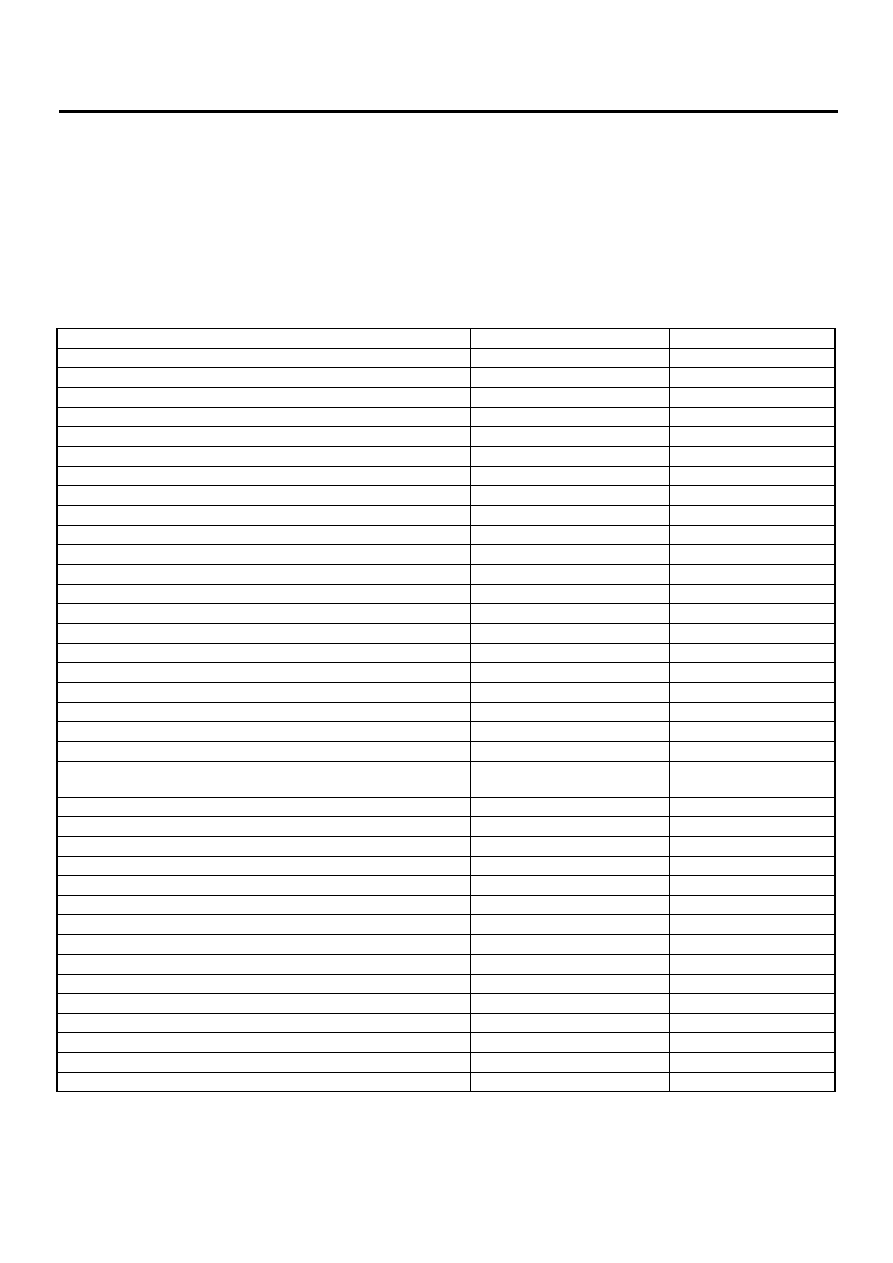
5. READ CURRENT DATA FOR ENGINE. (OBD MODE)
1) On the «Main Menu» display screen, select the {Each System Check} and press the [YES] key.
2) On the «System Selection Menu» display screen, select the {Engine Control System} and press the [YES]
key.
3) Press the [YES] key after displayed the information of engine type.
4) On the «Engine Diagnosis» display screen, select the {OBD System} and press the [YES] key.
5) On the «OBD Menu» display screen, select the {Current Data Display & Save} and press the [YES] key.
6) On the «Data Display Menu» display screen, select the {Data Display} and press the [YES] key.
7) Using the scroll key, move the display screen up or down until the desired data is shown.
• A list of the support data is shown in the following table.
NOTE:
For detailed operation procedure, refer to the SUBARU SELECT MONITOR OPERATION MANUAL.
Contents
Display
Unit of measure
Number of diagnosis code
Number of Diag Code:
—
Malfunction indicator lamp status
MI (MI)
ON or OFF
Monitoring test of misfire
Misfire monitoring
Complete or incomplete
Monitoring test of fuel system
Fuel system monitoring
Complete or incomplete
Monitoring test of comprehensive component
Component monitoring
Complete or incomplete
Test of catalyst
Catalyst Diagnosis
Complete or incomplete
Test of heated catalyst
Heated catalyst
No support
Test of evaporative emission purge control system
Evaporative purge system
No support
Test of secondary air system
Secondary air system
No support
Test of air conditioning system refrigerant
A/C system refrigerant
No support
Test of oxygen sensor (Bank 1, Bank 2, Rear)
Oxygen sensor
Complete or incomplete
Test of oxygen sensor heater (Bank 1, Bank 2, Rear)
O2 Heater Diagnosis
Complete or incomplete
Test of EGR system
EGR Diagnosis
Complete or incomplete
Air fuel ratio control system for bank 1
Fuel System for Bank 1
C1 normal
Air fuel ratio control system for bank 2
Fuel System for Bank 2
C1 normal
Engine load data
Calculated load valve
%
Engine coolant temperature signal
Coolant Temp.
°
C or
°
F
Short term fuel trim by front oxygen (A/F) sensor bank 1
Short term fuel trim B1
%
Long term fuel trim by front oxygen (A/F) sensor bank 1
Long term fuel trim B1
%
Short term fuel trim by front oxygen (A/F) sensor bank 2
Short term fuel trim B2
%
Long term fuel trim by front oxygen (A/F) sensor bank 2
Long term fuel trim B2
%
Intake manifold absolute pressure signal
Mani. Absolute Pressure
mmHg or kPa or inHg or
psig
Engine speed signal
Engine Speed
rpm
Vehicle speed signal
Vehicle Speed
km/h or MPH
Ignition timing for #1 cylinder
Ignition timing #1
°
Intake air temperature signal
Intake Air Temp.
°
C or
°
F
Throttle position signal
Throttle Opening Angle
%
Oxygen sensor output signal
Oxygen Sensor #12
V
Air fuel ratio correction by rear oxygen sensor
Short term fuel trim #12
%
On-board diagnostic system
OBD System
—
Oxygen sensor equipment
Oxygen Sensor #11
Supported
Oxygen sensor equipment
Oxygen Sensor #12
Supported
Oxygen sensor equipment
Oxygen Sensor #21
Supported
A/F sensor equipment
A/F Sensor #11
—
A/F sensor output signal
A/F Sensor #11
V
A/F sensor equipment
A/F Sensor #21
—
A/F sensor output signal
A/F Sensor #21
V
EN(H6DO)-41
ENGINE (DIAGNOSTICS)
SUBARU SELECT MONITOR
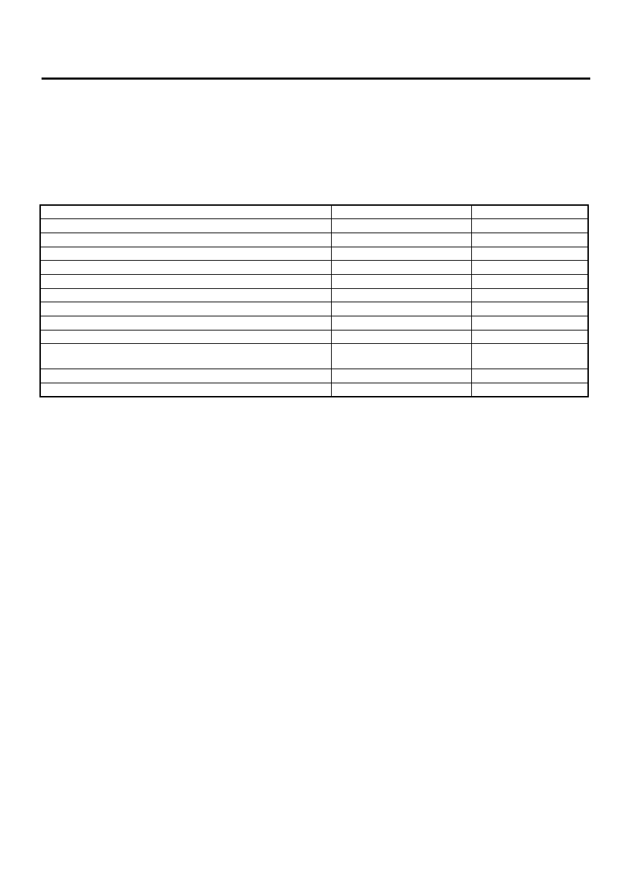
6. READ FREEZE FRAME DATA FOR ENGINE. (OBD MODE)
1) On the «Main Menu» display screen, select the {Each System Check} and press the [YES] key.
2) On the «System Selection Menu» display screen, select the {Engine Control System} and press the [YES]
key.
3) Press the [YES] key after displayed the information of engine type.
4) On the «Engine Diagnosis» display screen, select the {OBD System} and press the [YES] key.
5) On the «OBD Menu» display screen, select the {Freeze Frame Data} and press the [YES] key.
• A list of the support data is shown in the following table.
NOTE:
For detailed operation procedure, refer to the SUBARU SELECT MONITOR OPERATION MANUAL.
Contents
Display
Unit of measure
Diagnostic trouble code (DTC) for freeze frame data
Freeze frame data
DTC
Air fuel ratio control system for bank 1
Fuel system for Bank1
ON or OFF
Air fuel ratio control system for bank 2
Fuel System for Bank 2
ON or OFF
Engine load data
Engine Load
%
Engine coolant temperature signal
Coolant Temp.
°
C or
°
F
Short term fuel trim by front oxygen (A/F) sensor bank 1
Short term fuel trim B1
%
Long term fuel trim by front oxygen (A/F) sensor bank 1
Long term fuel trim B1
%
Short term fuel trim by front oxygen (A/F) sensor bank 2
Short term fuel trim B2
%
Long term fuel trim by front oxygen (A/F) sensor bank 2
Long term fuel trim B2
%
Intake manifold absolute pressure signal
Mani. Absolute Pressure
mmHg or kPa or inHg or
psi
Engine speed signal
Engine Speed
rpm
Vehicle speed signal
Vehicle Speed
km/h or MPH
Нет комментариевНе стесняйтесь поделиться с нами вашим ценным мнением.
Текст