Subaru Legacy III (2000-2003 year). Service manual — part 537
AT-42
AUTOMATIC TRANSMISSION
AUTOMATIC TRANSMISSION ASSEMBLY
29) Place transmission jack under transmission.
NOTE:
Make sure that the support plates of transmission
jack don't touch the oil pan.
30) Remove transmission rear crossmember from
vehicle.
31) Remove transmission.
CAUTION:
Move transmission and torque converter as a
unit away from engine.
32) Separate transmission assembly and rear
cushion rubber.
B: INSTALLATION
1) Install rear cushion rubber to transmission as-
sembly.
Tightening torque:
39 N·m (4.0 kgf-m, 29 ft-lb)
2) Install ST to torque converter clutch case.
ST
498277200
STOPPER SET
3) Install transmission onto engine.
(1) Gradually raise transmission with transmis-
sion jack.
(2) Engage them at splines.
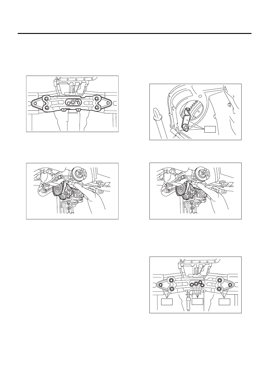
4) Install transmission rear crossmember.
Tightening torque:
T1: 35 N·m (3.6 kgf-m, 26 ft-lb)
T2: 70 N·m (7.1 kgf-m, 51 ft-lb)
5) Take off transmission jack.
AT-00687
AT-00109
AT-00103
ST
AT-00109
T1
T2
T2
AT-00688
AT-43
AUTOMATIC TRANSMISSION
AUTOMATIC TRANSMISSION ASSEMBLY
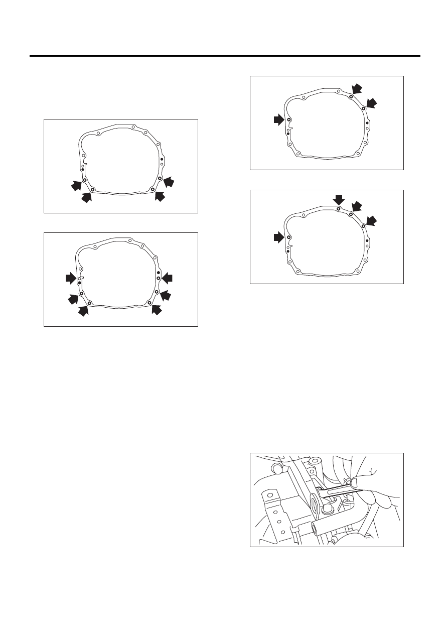
6) Tighten nuts and bolts which hold lower side of
transmission to engine.
Tightening torque:
50 N·m (5.1 kgf-m, 36.9 ft-lb)
Except 3.0 L model
3.0 L model
7) Lower the vehicle.
8) Connect engine and transmission.
(1) Remove ST from torque converter clutch
case.
NOTE:
Be careful not to drop the ST into the torque con-
verter clutch case when removing ST.
ST
498277200
STOPPER SET
(2) Install starter.
2.0 L non-TURBO and 2.5 L models
<Ref. to SC(H4SO)-6, INSTALLATION, Start-
er.>
3.0 L model
<Ref. to SC(H6DO)-6, INSTALLATION, Start-
er.>
2.0 L TURBO model
<Ref. to SC(H4DOSTC)-6, INSTALLATION,
Starter.>
(3) Tighten bolt which holds right upper side of
transmission to engine.
Tightening torque:
50 N·m (5.1 kgf-m, 36.9 ft-lb)
Except 3.0 L model
3.0 L model
9) Install torque converter clutch to drive plate.
(1) Tighten bolts which hold torque converter
clutch to drive plate.
(2) Tighten other bolts while rotating the engine
by using ST.
NOTE:
Be careful not to drop bolts into torque converter
clutch housing.
• Except 2.0 L model
ST
499977100
CRANKSHAFT PULLEY
WRENCH
• 2.0 L model
ST
499977400
CRANKSHAFT PULLEY
WRENCH
Tightening torque:
25 N·m (2.5 kgf-m, 18.1 ft-lb)
(3) Clog plug onto service hole.
AT-00108
AT-00689
AT-00106
AT-00681
AT-00102
AT-44
AUTOMATIC TRANSMISSION
AUTOMATIC TRANSMISSION ASSEMBLY
10) Remove ST.
11) Install pitching stopper.
Tightening torque:
T1: 50 N·m (5.1 kgf-m, 37 ft-lb)
T2: 58 N·m (5.9 kgf-m, 43 ft-lb)
12) Lift-up the vehicle.
13) Install front drive shafts into transmission.
(1) Lift-up the vehicle.
(2) Install front drive shaft into transmission.
(3) New drive spring pin into chamfered hole of
drive shaft.
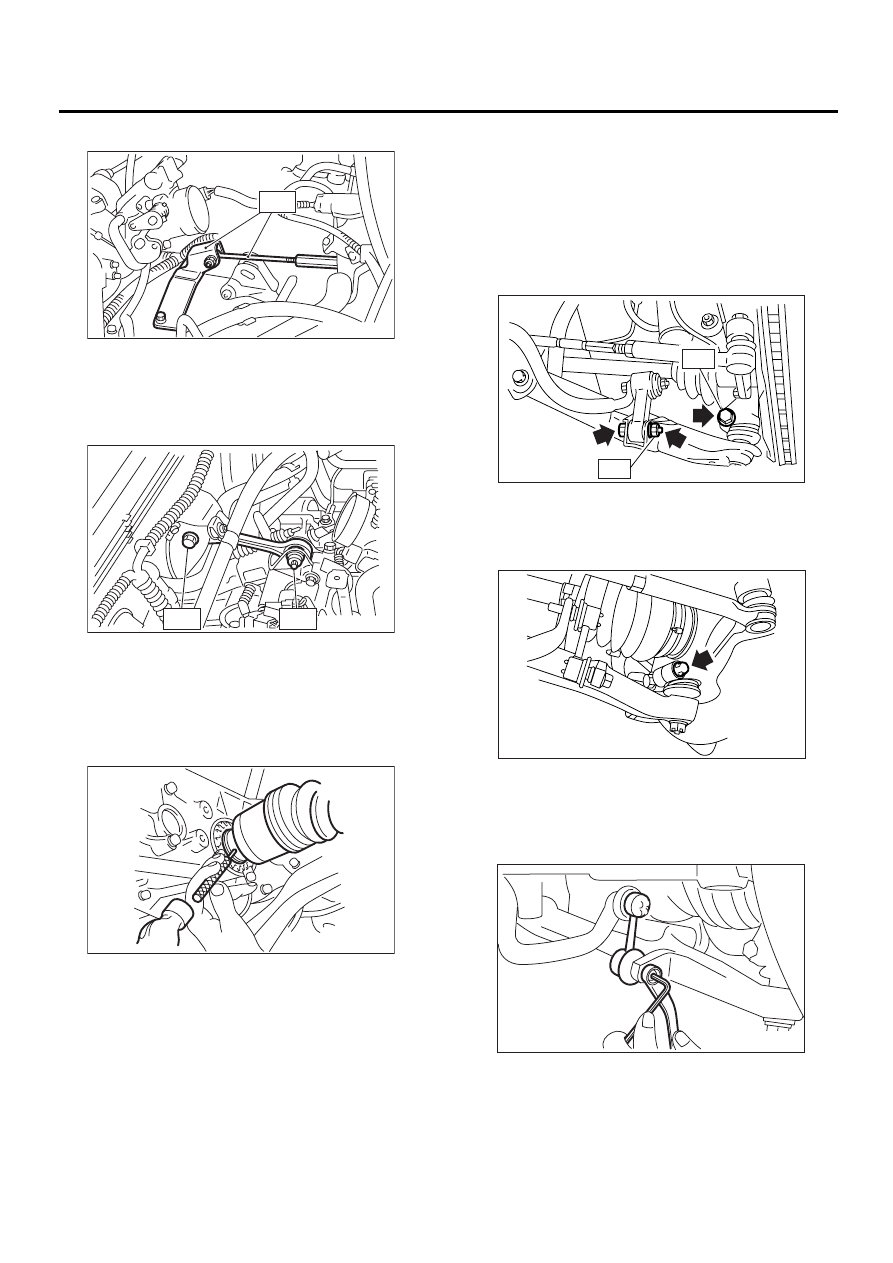
14) Install ball joint into housing.
15) Connect stabilizer link to transverse link, and
tighten bolts. (Non-TURBO model)
NOTE:
Discard loosened self-locking nut and replace with
a new one.
Tightening torque:
T1: 30 N·m (3.1 kgf-m, 22.4 ft-lb)
T2: 50 N·m (5.1 kgf-m, 37 ft-lb)
16) Tighten the installing bolts. (TURBO model)
Tightening torque:
50 N·m (5.1 kgf-m, 36.9 ft-lb)
17) Install the stabilizer link to transverse link.
(TURBO model)
Tightening torque:
45 N·m (4.6 kgf-m, 33.2 ft-lb)
18) Install shift select cable onto select lever.
<Ref. to CS-13, INSTALLATION, Select Cable.>
AT-00105
ST
AT-00691
T1
T2
AT-00685
AT-00692
T1
T2
AT-00809
AT-00810
AT-45
AUTOMATIC TRANSMISSION
AUTOMATIC TRANSMISSION ASSEMBLY
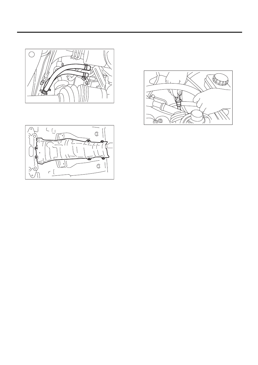
19) Install ATF level gauge guide, and connect ATF
cooler hoses to pipe.
20) Install propeller shaft.
<Ref. to DS-15, INSTALLATION, Propeller Shaft.>
21) Install heat shield cover.
22) Install rear exhaust pipe and muffler assembly.
2.0 L non-TURBO and 2.5 L with OBD models
<Ref. to EX(H4SO)-9, INSTALLATION, Rear Ex-
haust Pipe.> and <Ref. to EX(H4SO)-10, INSTAL-
LATION, Muffler.>
2.0 L non-TURBO and 2.5 L without OBD models
<Ref. to EX(H4SOw/oOBD)-13, INSTALLATION,
Rear Exhaust Pipe.> and <Ref. to EX(H4SOw/
oOBD)-14, INSTALLATION, Muffler.>
3.0 L model
<Ref. to EX(H6DO)-8, INSTALLATION, Rear Ex-
haust Pipe.> and <Ref. to EX(H6DO)-9, INSTAL-
LATION, Muffler.>
2.0 L TURBO model
<Ref. to EX(H4DOSTC)-12, INSTALLATION, Rear
Exhaust Pipe.> and <Ref. to EX(H4DOSTC)-13,
INSTALLATION, Muffler.>
23) Install front and center exhaust pipe. (Non-
TURBO model)
2.0 L and 2.5 L with OBD models
<Ref. to EX(H4SO)-6, INSTALLATION, Front Ex-
haust Pipe.>
2.0 L and 2.5 L without OBD models
<Ref. to EX(H4SOw/oOBD)-10, INSTALLATION,
Front Exhaust Pipe.>
3.0 L model
<Ref. to EX(H6DO)-6, INSTALLATION, Front Ex-
haust Pipe.>
24) Install center exhaust pipe. (TURBO model)
<Ref. to EX(H4DOSTC)-8, INSTALLATION, Cen-
ter Exhaust Pipe.>
25) Install under cover.
26) Lower the vehicle.
27) Install ATF level gauge.
28) Connect the following connectors.
(1) Transmission harness connectors
(2) Transmission ground terminal
29) Connect the following cables.
(1) Cruise control cable (With cruise control ve-
hicles)
30) Install air cleaner case stay.
Tightening torque:
16 N·m (1.6 kgf-m, 11.6 ft-lb)
31) Install air cleaner case or air intake chamber.
(Non-TURBO model)
2.0 L and 2.5 L models
<Ref. to IN(H4SO)-6, INSTALLATION, Air Cleaner
Case.>
3.0 L model
<Ref. to IN(H6DO)-6, INSTALLATION, Air Intake
Chamber.>
32) Install air intake duct. (Non-TURBO model)
2.0 L and 2.5 L models
<Ref. to IN(H4SO)-7, INSTALLATION, Air Intake
Duct.>
3.0 L model
<Ref. to IN(H6DO)-7, INSTALLATION, Air Intake
Duct.>
33) Install intercooler. (TURBO model)
<Ref. to IN(H4DOSTC)-14, INSTALLATION, Inter-
cooler.>
34) Connect battery ground cable.
35) Fill ATF up to the middle of the “COLD” side on
level gauge by using the gauge hole. <Ref. to AT-
30, Automatic Transmission Fluid.>
36) Take off vehicle from lift arms.
37) Check select lever operation.
<Ref. to AT-49, INSPECTION, Inhibitor Switch.>
38) Check the ATF level. <Ref. to AT-30, Automat-
ic Transmission Fluid.>
39) Check road test.
<Ref. to AT-32, Road Test.>
AT-00683
AT-00682
AT-00693
Нет комментариевНе стесняйтесь поделиться с нами вашим ценным мнением.
Текст