Subaru Legacy III (2000-2003 year). Service manual — part 538
AT-46
AUTOMATIC TRANSMISSION
TRANSMISSION MOUNTING SYSTEM
10.Transmission Mounting Sys-
tem
A: REMOVAL
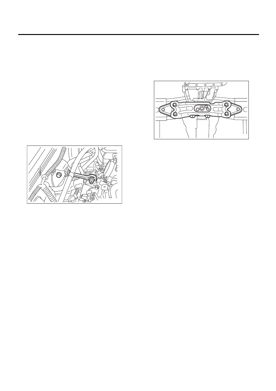
1. PITCHING STOPPER
1) Disconnect the ground cable from battery.
2) Remove the air cleaner case. (2.0 L non-TURBO
and 2.5 L models)
<Ref. to IN(H4SO)-6, REMOVAL, Air Cleaner
Case.>
3) Remove air intake chamber. (3.0 L model)
<Ref. to IN(H6DO)-6, REMOVAL, Air Intake Cham-
ber.>
4) Remove intercooler. (2.0 L TURBO model)
<Ref. to IN(H4DOSTC)-13, REMOVAL, Intercool-
er.>
5) Remove the pitching stopper.
2. CROSSMEMBER AND CUSHION RUB-
BER
1) Disconnect the ground cable from battery.
2) Jack-up the vehicle and support it with sturdy
racks.
3) Remove the front, center, rear exhaust pipes
and muffler. (Non-TURBO model)
2.0 L and 2.5 L with OBD models
<Ref. to EX(H4SO)-5, REMOVAL, Front Exhaust
Pipe.>, <Ref. to EX(H4SO)-9, REMOVAL, Rear
Exhaust Pipe.> and <Ref. to EX(H4SO)-10, RE-
MOVAL, Muffler.>
2.0 L and 2.5 L without OBD models
<Ref. to EX(H4SOw/oOBD)-9, REMOVAL, Front
Exhaust Pipe.>, <Ref. to EX(H4SOw/oOBD)-13,
REMOVAL, Rear Exhaust Pipe.> and <Ref. to
EX(H4SOw/oOBD)-14, REMOVAL, Muffler.>
3.0 L model
<Ref. to EX(H6DO)-5, REMOVAL, Front Exhaust
Pipe.>, <Ref. to EX(H6DO)-8, REMOVAL, Rear
Exhaust Pipe.> and <Ref. to EX(H6DO)-9, RE-
MOVAL, Muffler.>
4) Remove center and rear exhaust pipes, and
muffler. (TURBO model)
<Ref. to EX(H4DOSTC)-7, REMOVAL, Center Ex-
haust Pipe.>, <Ref. to EX(H4DOSTC)-12, RE-
MOVAL, Rear Exhaust Pipe.> and <Ref. to
EX(H4DOSTC)-13, REMOVAL, Muffler.>
5) Remove the heat shield cover.
6) Set the transmission jack under the transmis-
sion. Make sure that the support plates of transmis-
sion jack don't touch the oil pan.
7) Remove the transmission rear crossmember.
8) Remove the rear cushion rubber.
AT-00679
AT-00687
AT-47
AUTOMATIC TRANSMISSION
TRANSMISSION MOUNTING SYSTEM
B: INSTALLATION
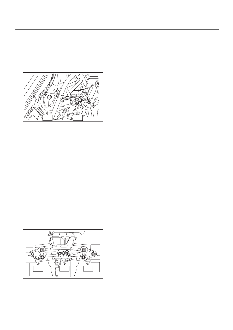
1. PITCHING STOPPER
1) Install the pitching stopper.
Tightening torque:
T1: 50 N·m (5.1 kgf-m, 37 ft-lb)
T2: 58 N·m (5.9 kgf-m, 43 ft-lb)
2) Install the air cleaner case. (2.0 L non-TURBO
and 2.5 L models)
<Ref. to IN(H4SO)-6, INSTALLATION, Air Cleaner
Case.>
3) Remove air intake chamber. (3.0 L model)
<Ref. to IN(H6DO)-6, INSTALLATION, Air Intake
Chamber.>
4) Remove intercooler. (TURBO model)
<Ref. to IN(H4DOSTC)-14, INSTALLATION, Inter-
cooler.>
2. CROSSMEMBER AND CUSHION RUB-
BER
1) Install the rear cushion rubber.
Tightening torque:
39 N·m (4.0 kgf-m, 29 ft-lb)
2) Install the crossmember.
Tightening torque:
T1: 35 N·m (3.6 kgf-m, 26 ft-lb)
T2: 70 N·m (7.1 kgf-m, 51 ft-lb)
3) Remove the transmission jack.
4) Install the heat shield cover.
5) Install the front, center, rear exhaust pipes and
the muffler. (Non-TURBO model)
With OBD
<Ref. to EX(H4SO)-6, INSTALLATION, Front Ex-
haust Pipe.>, <Ref. to EX(H4SO)-9, INSTALLA-
TION, Rear Exhaust Pipe.> and <Ref. to
EX(H4SO)-10, INSTALLATION, Muffler.>
Without OBD
<Ref. to EX(H4SOw/oOBD)-10, INSTALLATION,
Front Exhaust Pipe.>, <Ref. to EX(H4SOw/oOBD)-
13, INSTALLATION, Rear Exhaust Pipe.> and
<Ref. to EX(H4SOw/oOBD)-14, INSTALLATION,
Muffler.>
3.0 L model
<Ref. to EX(H6DO)-6, INSTALLATION, Front Ex-
haust Pipe.>, <Ref. to EX(H6DO)-8, INSTALLA-
TION, Rear Exhaust Pipe.> and <Ref. to
EX(H6DO)-9, INSTALLATION, Muffler.>
6) Install center and rear exhaust pipes, and muf-
fler. (TURBO model)
<Ref. to EX(H4DOSTC)-8, INSTALLATION, Cen-
ter Exhaust Pipe.>, <Ref. to EX(H4DOSTC)-12, IN-
STALLATION, Rear Exhaust Pipe.> and <Ref. to
EX(H4DOSTC)-13, INSTALLATION, Muffler.>
C: INSPECTION
Repair or replace parts if the results of the inspec-
tion below are not satisfactory.
1. PITCHING STOPPER
Make sure that the pitching stopper is not bent or
damaged. Make sure that the rubber is not stiff,
cracked, or otherwise damaged.
2. CROSSMEMBER AND CUSHION RUB-
BER
Make sure that the crossmember is not bent or
damaged. Make sure that the cushion rubber is not
stiff, cracked, or otherwise damaged.
AT-00691
T1
T2
T1
T2
T2
AT-00688
AT-48
AUTOMATIC TRANSMISSION
EXTENSION CASE OIL SEAL
11.Extension Case Oil Seal
A: INSPECTION
Make sure the ATF does not leak from the joint of
transmission or propeller shaft. If so, replace the oil
seal. <Ref. to AT-48, REPLACEMENT, Extension
Case Oil Seal.>
B: REPLACEMENT
1) Clean the transmission exterior.
2) Drain the ATF completely.
3) Replace the gasket with a new one, and then
tighten the ATF drain plug.
Tightening torque:
25 N·m (2.5 kgf-m, 18.1 ft-lb)
4) Remove the rear exhaust pipe and muffler.
2.0 L non-TURBO and 2.5 L with OBD models
<Ref. to EX(H4SO)-9, REMOVAL, Rear Exhaust
Pipe.> and <Ref. to EX(H4SO)-10, REMOVAL,
Muffler.>
2.0 L non-TURBO and 2.5 L without OBD models
<Ref. to EX(H4SOw/oOBD)-13, REMOVAL, Rear
Exhaust Pipe.> and <Ref. to EX(H4SOw/oOBD)-
14, REMOVAL, Muffler.>
3.0 L model
<Ref. to EX(H6DO)-8, REMOVAL, Rear Exhaust
Pipe.> and <Ref. to EX(H6DO)-9, REMOVAL, Muf-
fler.>
2.0 L TURBO model
MOVAL, Muffler.>
5) Remove the heat shield cover. (If equipped)
6) Remove the propeller shaft. <Ref. to DS-14, RE-
MOVAL, Propeller Shaft.>
7) Using the ST, remove the oil seal.
ST
398527700
PULLER ASSY
8) Using the ST, install the oil seal.
ST
498057300
INSTALLER
9) Install the propeller shaft. <Ref. to DS-15, IN-
STALLATION, Propeller Shaft.>
10) Install the heat shield cover.
11) Install the rear exhaust pipe and muffler.
2.0 L non-TURBO and 2.5 L with OBD models
<Ref. to EX(H4SO)-9, INSTALLATION, Rear Ex-
haust Pipe.> and <Ref. to EX(H4SO)-10, INSTAL-
LATION, Muffler.>
2.0 L non-TURBO and 2.5 L without OBD models
<Ref. to EX(H4SOw/oOBD)-13, INSTALLATION,
Rear Exhaust Pipe.> and <Ref. to EX(H4SOw/
oOBD)-14, INSTALLATION, Muffler.>
3.0 L model
<Ref. to EX(H6DO)-8, INSTALLATION, Rear Ex-
haust Pipe.> and <Ref. to EX(H6DO)-9, INSTAL-
LATION, Muffler.>
2.0 L TURBO model
STALLATION, Muffler.>
12) Pour ATF and check the ATF level. <Ref. to
AT-30, Automatic Transmission Fluid.>
(A) Oil pan
(B) Drain plug
(C) Differential oil drain plug
AT-00016
( A )
( B )
( C )
AT-49
AUTOMATIC TRANSMISSION
INHIBITOR SWITCH
12.Inhibitor Switch
A: INSPECTION
When the driving condition or starter motor opera-
tion is erroneous, first check the shift linkage for im-
proper operation. If the shift linkage is functioning
properly, check the inhibitor switch.
1) Disconnect the inhibitor switch connector.
2) Check continuity in inhibitor switch circuits with
the select lever moved to each position.
Also check that continuity in ignition circuit does not
exist when the select lever is in “R”, “D”, “3”, “2” and
“1” ranges.
If the inhibitor switch is inoperative, check for poor
contact of connector on transmission side.
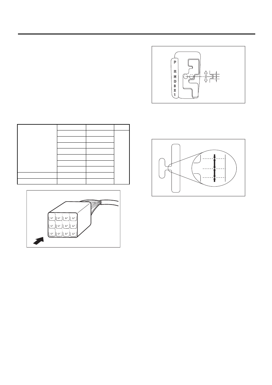
3) Check if there is continuity at equal points when
the select lever is turned 1.5
°
in both directions
from “N” range.
If there is continuity in one direction and the conti-
nuity in the other or if there is continuity at unequal
points, adjust the inhibitor switch. <Ref. to AT-50,
ADJUSTMENT, Inhibitor Switch.>
• Except model with SPORT shift
• Model with SPORT shift
4) Repeat the above checks. If there are abnormal-
ities, adjust the select cable. <Ref. to CS-14, AD-
JUSTMENT, Select Cable.>
Signal sent to TCM
Position
Pin No.
Value
P
4 — 3
Less
than
1
Ω
R
4 — 2
N
4 — 1
D
4 — 8
3
4 — 7
2
4 — 6
1
4 — 5
Ignition circuit
P/N
12 — 11
Back-up light circuit
R
10 — 9
Inhibitor switch side connector
AT-00030
( 1 )
( 2 )
( 3 )
( 4 )
( 5 )
( 6 )
( 7 )
( 8 )
( 9 )
(10)
(11)
(12)
(A) Continuity does not exist.
(B) Continuity exists.
(C) 1.5
°
(A) Continuity does not exist.
(B) Continuity exists.
(C) 1.5
°
AT-00452
( A )
( C )
( A )
( C )
( B )
AT-00800
( B )
( B )
( A )
( A )
( C )
( C )
0
D
+
P
R
N
D
3
1
2
-
Нет комментариевНе стесняйтесь поделиться с нами вашим ценным мнением.
Текст