Subaru Legacy III (2000-2003 year). Service manual — part 746
VDC-20
VDC (DIAGNOSTICS)
SUBARU SELECT MONITOR
7. Subaru Select Monitor
A: OPERATION
1. READ DIAGNOSTIC TROUBLE CODE
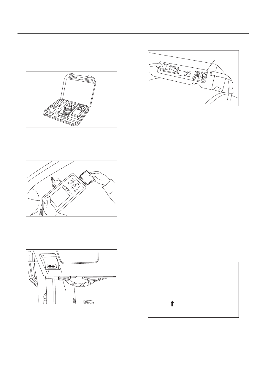
1) Prepare Subaru Select Monitor kit.
2) Connect diagnosis cable to Subaru Select Mon-
itor.
3) Insert cartridge into Subaru Select Monitor.
<Ref. to VDC-10, SPECIAL TOOLS, PREPARA-
TION TOOL, General Description.>
4) Connect Subaru Select Monitor to data link con-
nector.
(1) Data link connector located in the lower por-
tion of the instrument panel (on the driver's
side).
(2) Connect diagnosis cable to data link con-
nector.
5) Turn ignition switch to ON (engine OFF) and
Subaru Select Monitor switch to ON.
6) On the «Main Menu» display screen, select the
{Each System Check} and press the [YES] key.
7) On the «System Selection Menu» display
screen, select the {Brake Control System} and
press the [YES] key.
8) Press the [YES] key after displayed the informa-
tion of engine type.
9) On the «Brake Diagnosis» display screen, select
the {Diagnostic Code(s) Display} and press the
[YES] key.
10) On the «Diagnostic Code(s) Display» display
screen, select the {Current Diagnostic Code(s)} or
{History Diagnostic Code(s)} and press the [YES]
key.
NOTE:
• For detailed operation procedure, refer to the
SUBARU SELECT MONITOR OPERATION MAN-
UAL.
• For detailed concerning diagnostic trouble
codes, refer to the DIAGNOSTIC TROUBLE CODE
LIST.
<Ref. to VDC-27, List of Diagnostic Trouble Code
(DTC).>
• A maximum of 3 trouble codes are displayed in
order of occurrence.
*a* refers to the troubles in order of occurrence
(Latest, Old, Older).
(1) Data link connector
VDC00132
VDC00133
VDC00134
( 1 )
(1) Power switch
VDC00135
( 1 )
21 Front Right ABS Sensor Circuit
Open or Shorted Battery
( *a* )
VDC00154
VDC-21
VDC (DIAGNOSTICS)
SUBARU SELECT MONITOR
2. READ CURRENT DATA
1) On the «Main Menu» display screen, select
{Each System Check} and press the «YES» key.
2) On the «System Selection Menu» display
screen, select {Brake Control System} and press
«YES» key.
3) Press the «YES» key after the VDC type is dis-
played.
4) On the «Brake Control Diagnosis» display
screen, select {Current Data Display & Save} and
press the «YES» key.
5) On the «Data Display Menu» display screen, se-
lect {Data Display} and press the «YES» key.
6) Using the scroll key, move the display screen up
or down until the desired data is shown.
• A list of the support data is shown in the following
table.
NOTE:
For detailed operation procedure, refer to the SUBARU SELECT MONITOR OPERATION MANUAL.
Display screen
Contents to be monitored
Latest
The most recent trouble code appears
on the select monitor display.
Old
The second most recent trouble code
appears on the select monitor display.
Older
The third most recent trouble code
appears on the select monitor display.
Display screen
Contents to be monitored.
Unit of measure
FR wheel speed
Wheel speed detected by the Front Right ABS sensor is displayed.
km/h or MPH
FL wheel speed
Wheel speed detected by the Front Left ABS sensor is displayed.
km/h or MPH
RR wheel speed
Wheel speed detected by the Rear Right ABS sensor is displayed.
km/h or MPH
RL wheel speed
Wheel speed detected by the Rear Left ABS sensor is displayed.
km/h or MPH
Steering angle sensor
Steering wheel angle detected by the steering angle sensor is dis-
played.
deg
Yaw rate sensor
Vehicle's angular velocity detected by the yaw rate sensor is displayed.
deg/s
Lateral G sensor
Vehicle's lateral acceleration detected by the lateral G sensor is dis-
played.
V
Pressure sensor 1
Brake fluid pressure detected by the primary pressure sensor is dis-
played.
V
Pressure sensor 2
Brake fluid pressure detected by the secondary pressure sensor is dis-
played.
V
Longitudinal G sensor
Longitudinal G sensor is not equipped on vehicles after '00MY.
But longitudinal G sensor will remain on monitor and 0 V will be dis-
played.
V
ABS CM power voltage
Voltage supplied to VDCCM is displayed.
V
Torque driver requires
Engine torque requested by the driver is displayed.
N·m
Current torque
Current engine torque is displayed.
N·m
Valve relay signal
Drive condition of the valve relay is displayed.
ON or OFF
Motor relay signal
Drive condition of the motor relay is displayed.
ON or OFF
VDC OFF lamp
ON operation of the VDC OFF indicator lamp is displayed.
ON or OFF
Motor relay monitor
Operating condition of the motor relay is displayed.
High or Low
PW signal
Accelerator position signal is displayed.
1 or 0
AET signal
Engine control start signal is displayed.
OPEN or GND
AEB signal
Engine control signal is displayed.
OPEN or GND
AEC signal
Engine control signal is displayed.
OPEN or GND
EAM signal
Engine control command signal is displayed.
1 or 0
VDC-22
VDC (DIAGNOSTICS)
SUBARU SELECT MONITOR
3. CLEAR MEMORY MODE
1) On the «Main Menu» display screen, select {2.
Each System Check} and press the «YES» key.
2) On the «System Select Menu» display screen,
select {Brake System} and press the «YES» key.
3) Press the «YES» key after the engine type is dis-
played.
4) On the «Brake Control Diagnosis» display
screen, select {Clear Memory} and press the
«YES» key.
5) When `Done' and `turn ignition switch OFF' are
shown on the display screen, turn the Subaru Se-
lect Monitor and ignition switch to OFF.
NOTE:
For detailed operation procedure, refer to the SUB-
ARU SELECT MONITOR OPERATION MANUAL.
4. FUNCTION CHECK
Display screen
Contents to be monitored
Index No.
ABS sequence control mode
Perform ABS sequence control by operating
valve and pump motor sequentially.
<Ref. to VDC-16, ABS Sequence Control.>
VDC check mode
Perform VDC sequence control by operating
valve and pump motor sequentially.
<Ref. to VDC-19, VDC Sequence Control.>
Set mode St. r. A. Sen. N &
Lat. G Sen. Op
Set both the neutral position of the steering
angle sensor and the zero “0” point of the lateral
G sensor.
VDC-23
VDC (DIAGNOSTICS)
READ DIAGNOSTIC TROUBLE CODE (DTC)
8. Read Diagnostic Trouble
Code (DTC)
A: OPERATION
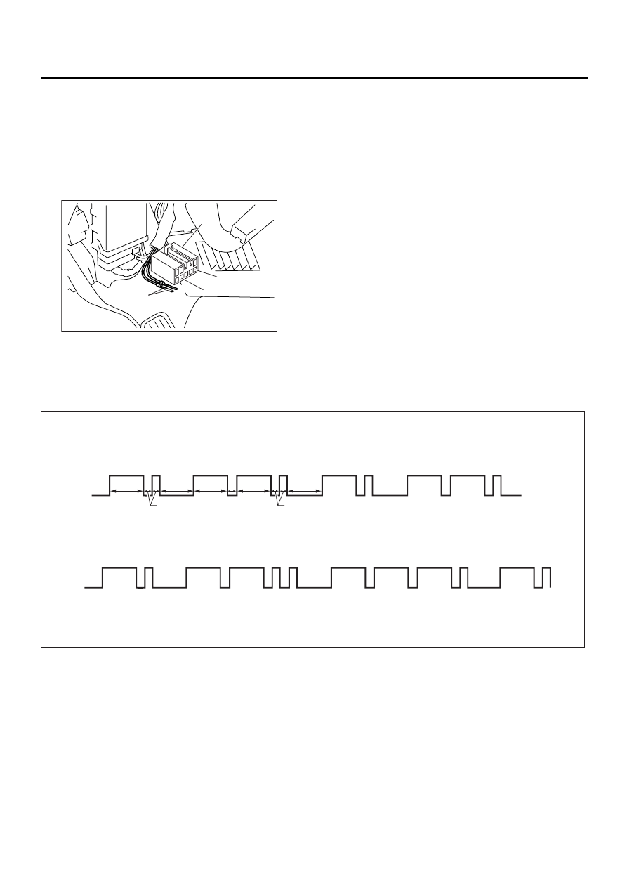
1. WITHOUT SUBARU SELECT MONITOR
1) Take out diagnosis connector from side of driv-
er's seat heater unit.
2) Turn ignition switch OFF.
3) Connect diagnosis connector terminal 8 to diag-
nosis terminal.
4) Turn ignition switch ON.
5) ABS warning light is set in the diagnostic mode
and blinks to identify diagnostic trouble code
(DTC).
6) After the start code (11) is shown, the diagnostic
trouble codes (DTCs) will be shown in order of the
last information first.
These repeat for a maximum of 5 minutes.
NOTE:
• When there are no diagnostic trouble codes
(DTCs) in memory, only the start code (11) is
shown.
• When on-board diagnosis of the VDC control
module detects a problem, the information (up to a
maximum of three) will be stored in the EEP ROM
as a diagnostic trouble code (DTC). When there
are more than three, the most recent three will be
stored. (Stored codes will stay in memory until they
are cleared.)
2. WITH SUBARU SELECT MONITOR
Refer to SUBARU SELECT MONITOR for informa-
tion about how to obtain and understand diagnostic
trouble codes (DTCs). <Ref. to VDC-20, Subaru
Select Monitor.>
(1) Diagnosis connector
(2) Diagnosis terminal
(3) 8 terminal
(4) 5 terminal
( 1 )
( 2 )
( 3 )
( 4 )
VDC00136
VDC00137
ON
OFF
ON
OFF
1
1
1
2
2
1
1
1
1
1
2
2
1
1
1
3
1.2 sec
1.2 sec
1.2 sec
1.0 sec
1.0 sec
0.3 sec
0.3 sec
0.3 sec
DTC: 22,31
DTC: 21
DTC: 21
DTC: 22
DTC: 31
DTC: 21
Example of DTC indication
Start code
Start code
Start code
Нет комментариевНе стесняйтесь поделиться с нами вашим ценным мнением.
Текст