Subaru Legacy III (2000-2003 year). Service manual — part 744
VDC-12
VDC (DIAGNOSTICS)
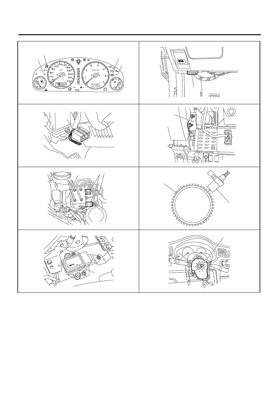
ELECTRICAL COMPONENTS LOCATION
VDC00156
( 6 )
( 7 )
( 8 )
( 9 )
VDC00169
(11)
VDC00166
( 5 )
VDC00157
(17)
VDC00167
( 1 )
(18)
VDC00170
(12)
(13)
VDC00168
(15)
VDC00171
(10)
VDC-13
VDC (DIAGNOSTICS)
CONTROL MODULE I/O SIGNAL
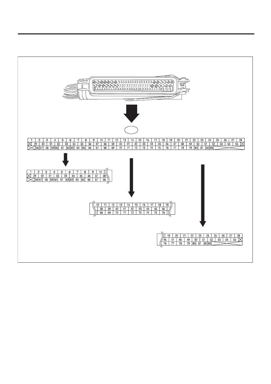
5. Control Module I/O Signal
A: ELECTRICAL SPECIFICATION
NOTE:
• The terminal numbers in the VDC control module connector are as shown in the figure.
• When the connector is removed from the VDCCM, the connector switch closes the circuit between terminal
No. 53, No. 54 and No. 55. The ABS and VDC warning light illuminate.
VDC00125
F87
VDC-14
VDC (DIAGNOSTICS)
CONTROL MODULE I/O SIGNAL
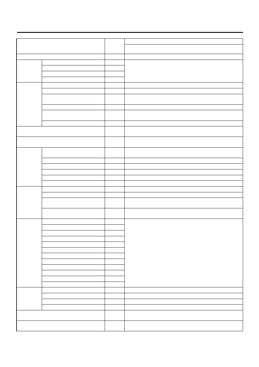
Contents
Terminal
No.
(+)—(
−
)
Input/Output signal
Measured value and measuring condition
Ignition switch
28—1
10 — 15 V when ignition switch is ON.
ABS sensor
(Wheel
speed sen-
sor)
Front left wheel
49—19
0.12 — 1 V (When it is 20 Hz.)
Front right wheel
14—15
Rear left wheel
16—17
Rear right wheel
18—46
Yaw rate
and lateral
G sensor
Output (Lateral G sensor)
70—64
2.2 — 2.8 V when vehicle is in horizontal position.
Power supply
63—64
10 — 15 V when ignition switch is ON.
Output (Yaw rate sensor)
65—64
Wave form <Ref. to VDC-17, WAVEFORM, MEASUREMENT,
Reference (Yaw rate sensor)
66—64
2.1 — 2.9 V
Test
67—64
40 ms pulse signal with a cycle of 5 — 1 V <Ref. to VDC-17,
WAVEFORM, MEASUREMENT, Control Module I/O Signal.>
Ground
64
—
CAN communication line (+)
81—1
2.5 — 1.5 V pulse signal <Ref. to VDC-17, WAVEFORM, MEA-
SUREMENT, Control Module I/O Signal.>
CAN communication line (
−
)
83—1
3.5 — 2.5 V pulse signal <Ref. to VDC-17, WAVEFORM, MEA-
SUREMENT, Control Module I/O Signal.>
Engine
module
AET
21—1
1.5 V or less (ABS/TCS/VDC operating); 10 V or more (ABS/TCS/
VDC not operating)
AEB
43—1
10 — 15 V (Ignition switch ON and vehicle at standstill)
AEC
8—1
10 — 15 V (Ignition switch ON and vehicle at standstill)
EAS
75—1
3.5 — 1.5 V pulse signal
EAC
45—1
3.5 — 1.5 V pulse signal
Revolution
9—1
10 — 1.5 V pulse signal
Relay box
Valve relay power supply
27—1
10 — 15 V when ignition switch is ON.
Valve relay coil
47—1
Less than 1.5 V when ignition switch is ON.
Motor relay coil
22—1
1.5 V or less (ABS/TCS/VDC operating); 10 V or more (ABS/TCS/
VDC not operating)
Motor monitoring
10—1
10 V or less (ABS/TCS/VDC operating); 1.5 V or more (ABS/TCS/
VDC not operating)
Hydraulic
control unit
Front left inlet solenoid valve
24—1
10 — 15 V when the valve is OFF and less than 1.5 V when the
valve is ON.
Front right inlet solenoid valve
30—1
Rear left inlet solenoid valve
31—1
Rear right inlet solenoid valve
23—1
Front left outlet solenoid valve
51—1
Front right outlet solenoid valve
3—1
Rear left outlet solenoid valve
4—1
Rear right outlet solenoid valve
50—1
Primary cut solenoid valve
25—1
Secondary cut solenoid valve
26—1
Primary suction solenoid valve
29—1
Secondary suction solenoid valve
2—1
Pressure
sensor
Power supply
78—76
4.75 — 5.25 V when ignition switch is ON.
Primary output
77—76
0.48 — 0.72 V (Brake pedal released)
Ground
76
—
Secondary output
36—76
0.48 — 0.72 V (Brake pedal released)
VDC operation indicator light
32—1
Less than 1.5 V during 1.5 seconds when ignition switch is ON,
and 10 — 15 V after 1.5 seconds.
VDC OFF indicator light
52—1
1.5 V or less (Ignition switch ON and VDC OFF indicator light ON);
10 — 15 V (Ignition switch ON and VDC OFF indicator light OFF)

VDC-15
VDC (DIAGNOSTICS)
CONTROL MODULE I/O SIGNAL
VDC warning light
53—1
Less than 1.5 V during 1.5 seconds when ignition switch is ON,
and 10 — 15 V after 1.5 seconds.
ABS warning light
54—1
Less than 1.5 V during 1.5 seconds when ignition switch is ON,
and 10 — 15 V after 1.5 seconds.
Diagnosis
connector
Terminal No. 8
13
—
Terminal No. 5
74
—
Select moni-
tor
Data is received.
11—1
Less than 1.5 V when no data is received.
Data is sent.
38—1
4.75 — 5.25 V when no data is sent.
VDC OFF switch
40—1
10 — 15 V when ignition switch is ON.
0 V (While pushing the switch)
Ground
1
—
Ground
55
—
Нет комментариевНе стесняйтесь поделиться с нами вашим ценным мнением.
Текст