Subaru Legacy III (2000-2003 year). Service manual — part 496

EN(H4DOSTC)-154
ENGINE (DIAGNOSTICS)
DIAGNOSTIC PROCEDURE WITH DIAGNOSTIC TROUBLE CODE (DTC)
6
CHECK POOR CONTACT.
Check poor contact in ECM connector.
Is there poor contact in ECM connector?
There is poor contact.
Repair the poor
contact in ECM
connector.
Replace the ECM.
<Ref. to
FU(H4DOSTC)-
40, Engine Con-
trol Module.>
Step
Value
Yes
No
EN(H4DOSTC)-155
ENGINE (DIAGNOSTICS)
DIAGNOSTIC PROCEDURE WITH DIAGNOSTIC TROUBLE CODE (DTC)
MEMO:
EN(H4DOSTC)-156
ENGINE (DIAGNOSTICS)
DIAGNOSTIC PROCEDURE WITH DIAGNOSTIC TROUBLE CODE (DTC)
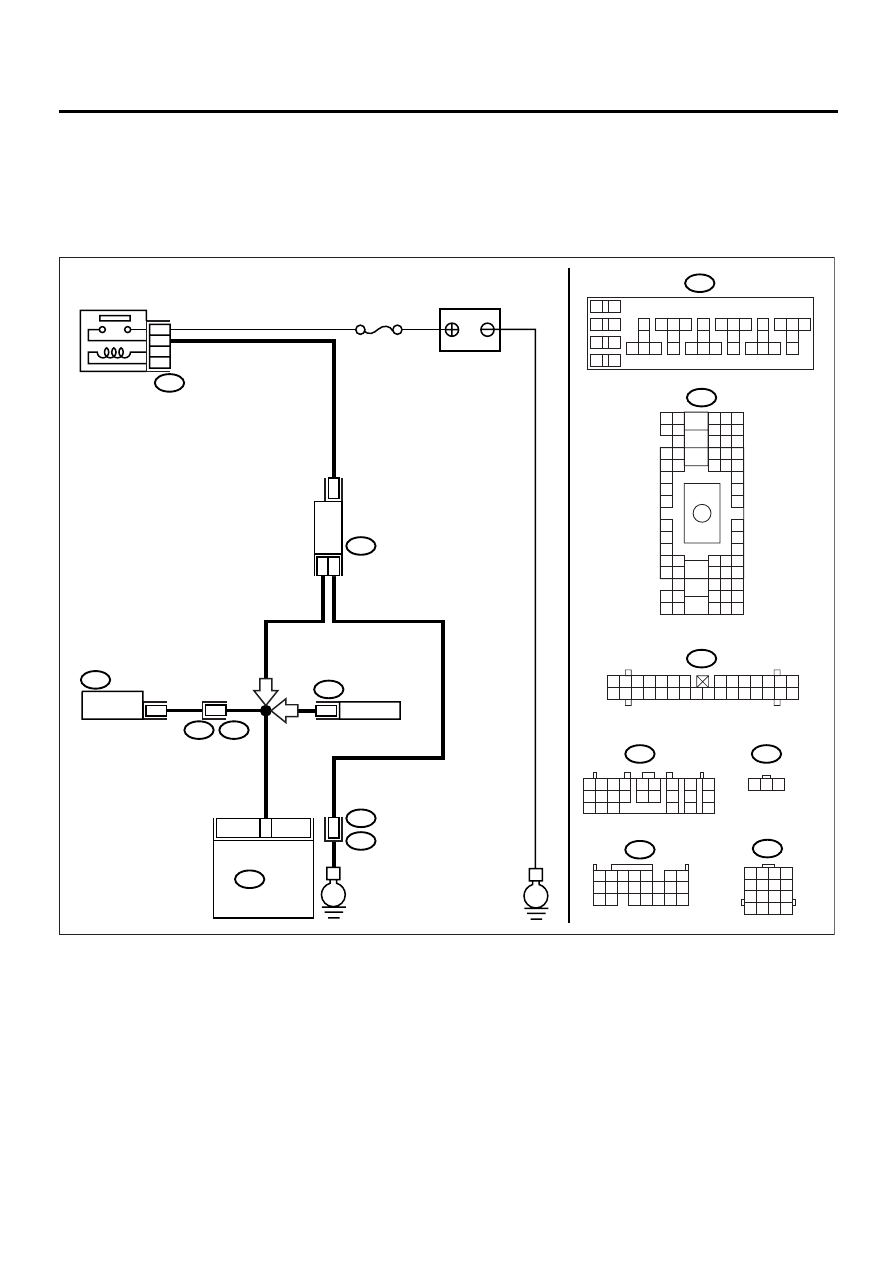
AG:DTC P0500 — VEHICLE SPEED SENSOR —
CAUTION:
After repair or replacement of faulty parts, conduct Clear Memory Mode <Ref. to EN(H4DOSTC)-35,
OPERATION, Clear Memory Mode.> and Inspection Mode <Ref. to EN(H4DOSTC)-33, Inspection
Mode.> .
• WIRING DIAGRAM:
EN-00946
E
E
i10
i10
i1
B36
B17
B22
E3
BATTERY
IGNITION
RELAY
COMBINATION
METER
B56
TRANSMISSION
CONTROL
MODULE
VEHICLE
SPEED
SENSOR
B134
B134
B56
B157
B157
ECM
38
37
1
No.15
B22
11
17
2
3
16
1
10
11 12 13
14 15 16
17
18
19
20
21 22 23
24 25 26
27
28
29
30
31 32 33
34 35 36
37
38
1
2
9
3
4
5
6
7
8
1 2 3 4
5 6 7 8
9 10 11 12
13 14 15 16
1 2 3 4
10 11 12
19 20 21
13
5
6
14 15
7
8 9
16 17
18
22
E4
B36
B4 B5 B6
A4 A5 A6
C5 C6
F6
D4 D5 D6
F1
H1
C4
G6
G1
C2
K1
M1 M2
K6
L1
D1 D2
A1 A2
B1 B2
I6
J6
L2
I1
J1
H6
M4 M5 M6
L4 L5 L6
N5 N6
O4 O5 O6
N4
P4 P5
N2
O1 O2
P1 P2
N3
O3
P3
P6
A3
B3
C3
E4 E5 E6
E1 E2
1 2 3
B17
AT
MT
1 2 3 4 5 6 7
8 9 10 11 12 13 14
15 16 17 18 19 20 21 22 23 24 25 26 27 28 29 30
1 2
7
8
9
5 6
3 4
10 11 12
19 20 21
13
14 15
16
17
18
22
23
24
EN(H4DOSTC)-157
ENGINE (DIAGNOSTICS)
DIAGNOSTIC PROCEDURE WITH DIAGNOSTIC TROUBLE CODE (DTC)
Step
Value
Yes
No
1
CHECK SPEEDOMETER OPERATION IN
COMBINATION METER.
Does the speedometer operate normally?
Operates normally.
Check the speed-
ometer and vehi-
cle speed sensor.
<Ref. to IDI-19,
Speedometer.>
2
CHECK HARNESS BETWEEN ECM AND
COMBINATION METER CONNECTOR.
1) Turn the ignition switch to OFF.
2) Disconnect the connector from combination
meter.
3) Measure the resistance between ECM and
combination meter.
Connector & terminal
(B134) No. 1 — (i10) No. 11:
Is the measured value less than the speci-
fied value?
10
Ω
Repair the poor
contact in ECM
connector.
Repair the har-
ness and connec-
tor.
NOTE:
In this case, repair
the following:
• Open circuit in
harness between
ECM and combi-
nation meter con-
nector
• Poor contact in
ECM connector
• Poor contact in
combination meter
connector
• Poor contact in
coupling connector
Нет комментариевНе стесняйтесь поделиться с нами вашим ценным мнением.
Текст