Subaru Legacy III (2000-2003 year). Service manual — part 617
MT-36
MANUAL TRANSMISSION AND DIFFERENTIAL
MANUAL TRANSMISSION ASSEMBLY
6) Tighten nuts which hold lower side of transmis-
sion to engine.
Tightening torque:
50 N·m (5.1 kgf-m, 37 ft-lb)
7) Connect engine and transmission.
(1) Install starter.
Non-TURBO model
<Ref. to SC(H4SO)-6, INSTALLATION, Start-
er.>
TURBO model
<Ref. to SC(H4DOSTC)-6, INSTALLATION,
Starter.>
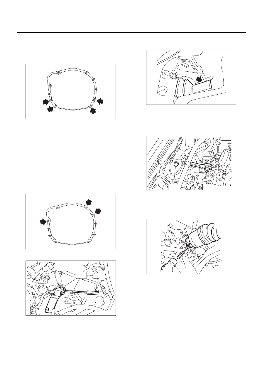
(2) Tighten bolt which holds right upper side of
transmission to engine.
Tightening torque:
50 N·m (5.1 kgf-m, 37 ft-lb)
8) Remove ST.
9) Push the clutch release lever to fit bearing into
clutch cover.
10) Install pitching stopper.
Tightening torque:
T1: 50 N·m (5.1 kgf-m, 37 ft-lb)
T2: 58 N·m (5.9 kgf-m, 43 ft-lb)
11) Lift up the vehicle.
12) Install front drive shafts into transmission.
13) New drive spring pin into chamfered hole of
drive shaft.
MT-00077
MT-00073
MT-00070
ST
MT-00383
T1
T2
MT-00358
MT-00357
MT-37
MANUAL TRANSMISSION AND DIFFERENTIAL
MANUAL TRANSMISSION ASSEMBLY
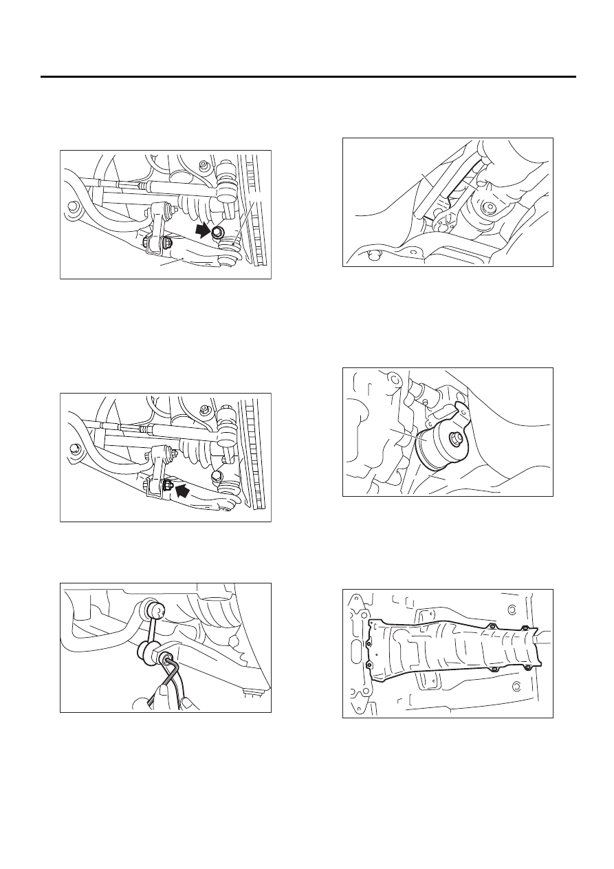
14) Install ball joints of lower arm into knuckle arm
of housing, and tighten installing bolts.
Tightening torque:
50 N·m (5.1 kgf-m, 37 ft-lb)
15) Install stabilizer link from transverse link.
Non-TURBO model
Tightening torque:
30 N·m (3.1 kgf-m, 22.1 ft-lb)
TURBO model
Tightening torque:
45 N·m (4.6 kgf-m, 33.2 ft-lb)
16) Connect rod to the joint.
Tightening torque:
18 N·m (1.8 kgf-m, 13.0 ft-lb)
17) Connect stay to transmission bracket.
Tightening torque:
18 N·m (1.8 kgf-m, 13.0 ft-lb)
18) Install propeller shaft. <Ref. to DS-15, INSTAL-
LATION, Propeller Shaft.>
19) Install heat shield cover. (If equipped)
(A) Transverse link
(B) Ball joint
MT-00086
( A )
( B )
MT-00359
MT-00076
(A) Joint
(B) Rod
(A) Stay
(B) Transmission bracket
MT-00089
( A )
( B )
MT-00360
( A )
( B )
MT-00355
MT-38
MANUAL TRANSMISSION AND DIFFERENTIAL
MANUAL TRANSMISSION ASSEMBLY
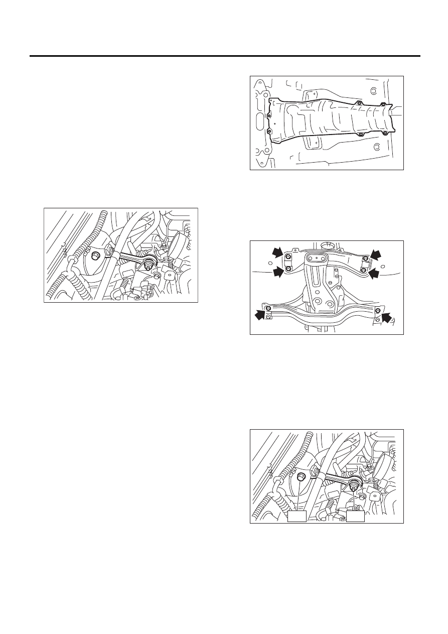
20) Install hanger bracket on right side of transmis-
sion.
21) Install front, center, rear, exhaust pipe and muf-
fler. (Non-TURBO model)
Without OBD
<Ref. to EX(H4SOw/oOBD)-10, INSTALLATION,
Front Exhaust Pipe.>, <Ref. to EX(H4SOw/
oOBD)-13, INSTALLATION, Rear Exhaust Pipe.>
and <Ref. to EX(H4SOw/oOBD)-14, INSTALLA-
TION, Muffler.>
With OBD
<Ref. to EX(H4SO)-6, INSTALLATION, Front Ex-
haust Pipe.>, <Ref. to EX(H4SO)-9, INSTALLA-
TION, Rear Exhaust Pipe.> and <Ref. to
EX(H4SO)-10, INSTALLATION, Muffler.>
22) Install center, rear exhaust pipe and muffler.
(TURBO model)
<Ref. to EX(H4DOSTC)-8, INSTALLATION, Cen-
ter Exhaust Pipe.>, <Ref. to EX(H4DOSTC)-12, IN-
STALLATION, Rear Exhaust Pipe.> and <Ref. to
EX(H4DOSTC)-13, INSTALLATION, Muffler.>
23) Install under cover.
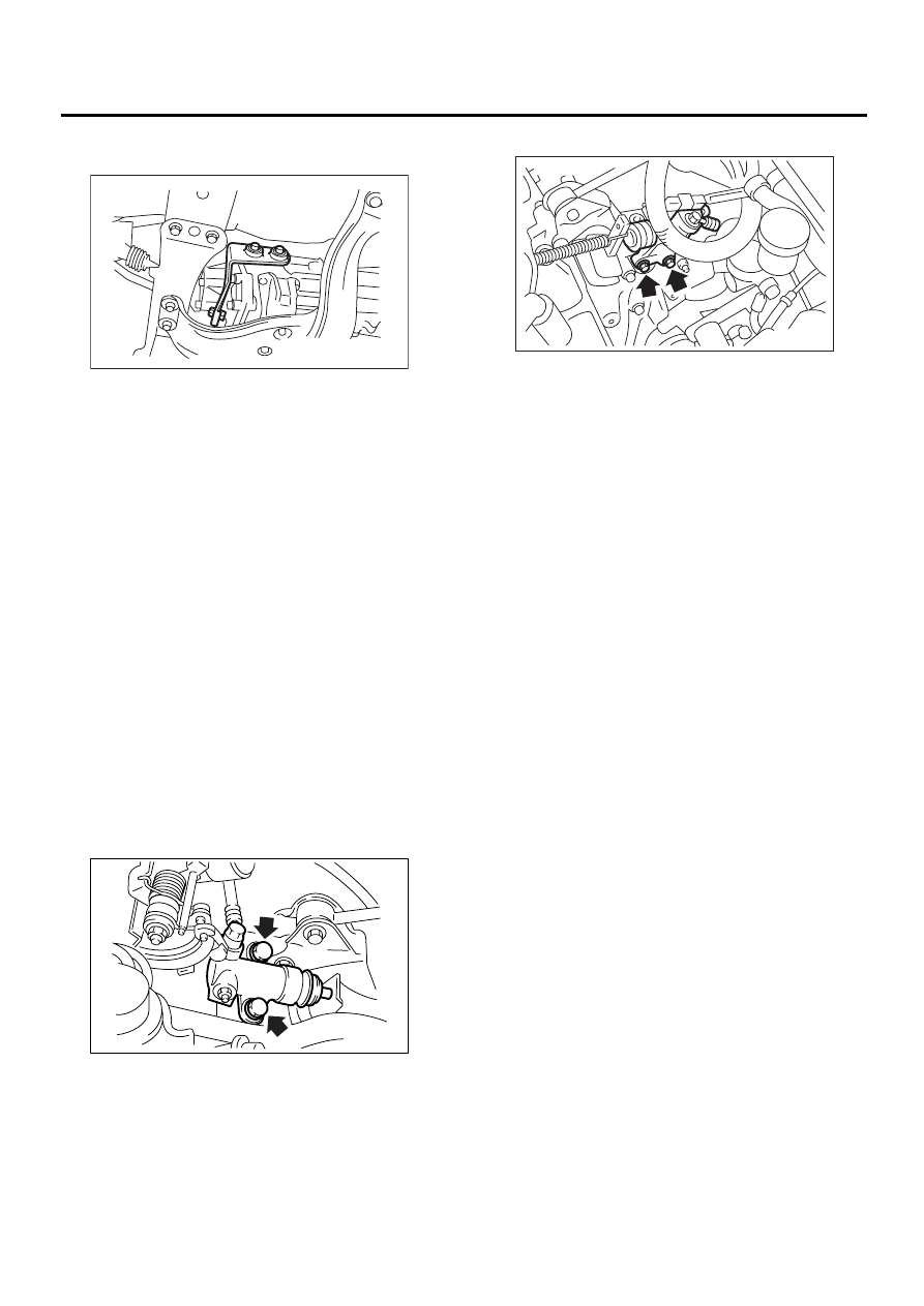
24) Install operating cylinder.
Tightening torque:
37 N·m (3.8 kgf-m, 27.5 ft-lb)
Non-TURBO model
TURBO model
25) Connect the following connectors.
(1) Transmission ground terminal
Tightening torque:
13 N·m (1.3 kgf-m, 9.4 ft-lb)
(2) Vehicle speed sensor connector
(3) Neutral position switch connector
(4) Back-up light switch connector
(5) High-low switch connector (Dual-range
model)
26) Install air cleaner case stay. (Non-TURBO
model)
Tightening torque:
16 N·m (1.6 kgf-m, 11.6 ft-lb)
27) Install air cleaner case and intake duct. (Non-
TURBO model)
<Ref. to IN(H4SO)-6, INSTALLATION, Air Cleaner
Case.> and <Ref. to IN(H4SO)-7, INSTALLATION,
Air Intake Duct.>
28) Install the intercooler. (Non-TURBO model)
<Ref. to IN(H4DOSTC)-14, INSTALLATION, Inter-
cooler.>
29) Connect battery ground cable.
30) Pour gear oil and check the oil level. <Ref. to
MT-31, Transmission Gear Oil.>
31) Take off vehicle from lift arms.
MT-00074
MT-00067
MT-00068
MT-39
MANUAL TRANSMISSION AND DIFFERENTIAL
TRANSMISSION MOUNTING SYSTEM
4. Transmission Mounting Sys-
tem
A: REMOVAL
1. PITCHING STOPPER
1) Disconnect battery ground cable.
2) Remove the air cleaner case. (Non-TURBO
model)
<Ref. to IN(H4SO)-6, REMOVAL, Air Cleaner
Case.>
3) Remove the intercoooler. (TURBO model)
<Ref. to IN(H4DOSTC)-13, REMOVAL, Intercool-
er.>
4) Remove the pitching stopper.
2. CROSSMEMBER AND CUSHION RUB-
BER
1) Disconnect battery ground cable.
2) Jack-up vehicle and support it with sturdy racks.
3) Remove the front, center, rear exhaust pipes
and muffler. (Non-TURBO model)
Without OBD
<Ref. to EX(H4SOw/oOBD)-9, REMOVAL, Front
Exhaust Pipe.>, <Ref. to EX(H4SOw/oOBD)-13,
REMOVAL, Rear Exhaust Pipe.> and <Ref. to
EX(H4SOw/oOBD)-14, REMOVAL, Muffler.>
With OBD
<Ref. to EX(H4SO)-5, REMOVAL, Front Exhaust
Pipe.>, <Ref. to EX(H4SO)-9, REMOVAL, Rear
Exhaust Pipe.> and <Ref. to EX(H4SO)-10, RE-
MOVAL, Muffler.>
4) Remove center, rear exhaust pipe and muffler.
(TURBO model)
<Ref. to EX(H4DOSTC)-7, REMOVAL, Center Ex-
haust Pipe.>, <Ref. to EX(H4DOSTC)-12, RE-
MOVAL, Rear Exhaust Pipe.> and <Ref. to
EX(H4DOSTC)-13, REMOVAL, Muffler.>
5) Remove the heat shield cover. (If equipped)
6) Set the transmission jack under the transmission
body.
CAUTION:
Always support transmission case with a trans-
mission jack.
7) Remove the rear crossmember.
8) Remove the rear cushion rubber.
B: INSTALLATION
1. PITCHING STOPPER
1) Install the pitching stopper.
Tightening torque:
T1: 50 N·m (5.1 kgf-m, 37 ft-lb)
T2: 58 N·m (5.9 kgf-m, 43 ft-lb)
2) Install the air cleaner case. (Non-TURBO model)
<Ref. to IN(H4SO)-6, INSTALLATION, Air Cleaner
Case.>
3) Install the intercooler. (TURBO model) <Ref. to
IN(H4DOSTC)-14, INSTALLATION, Intercooler.>
MT-00354
MT-00355
MT-00079
T1
T2
MT-00358
Нет комментариевНе стесняйтесь поделиться с нами вашим ценным мнением.
Текст