Subaru Legacy III (2000-2003 year). Service manual — part 616
MT-32
MANUAL TRANSMISSION AND DIFFERENTIAL
MANUAL TRANSMISSION ASSEMBLY
3. Manual Transmission As-
sembly
A: REMOVAL
1) Set vehicle on a lift.
2) Open front hood fully, and support with stay.
3) Disconnect battery ground cable.
4) Move shift lever to “N”, and release the parking
brake.
5) Remove air intake duct and cleaner case. (NA
model) <Ref. to IN(H4SO)-6, REMOVAL, Air
Cleaner Case.> and <Ref. to IN(H4SO)-7, RE-
MOVAL, Air Intake Duct.>
6) Remove the intercooler. (TURBO model) <Ref.
to IN(H4DOSTC)-13, REMOVAL, Intercooler.>
7) Remove air cleaner case stay.
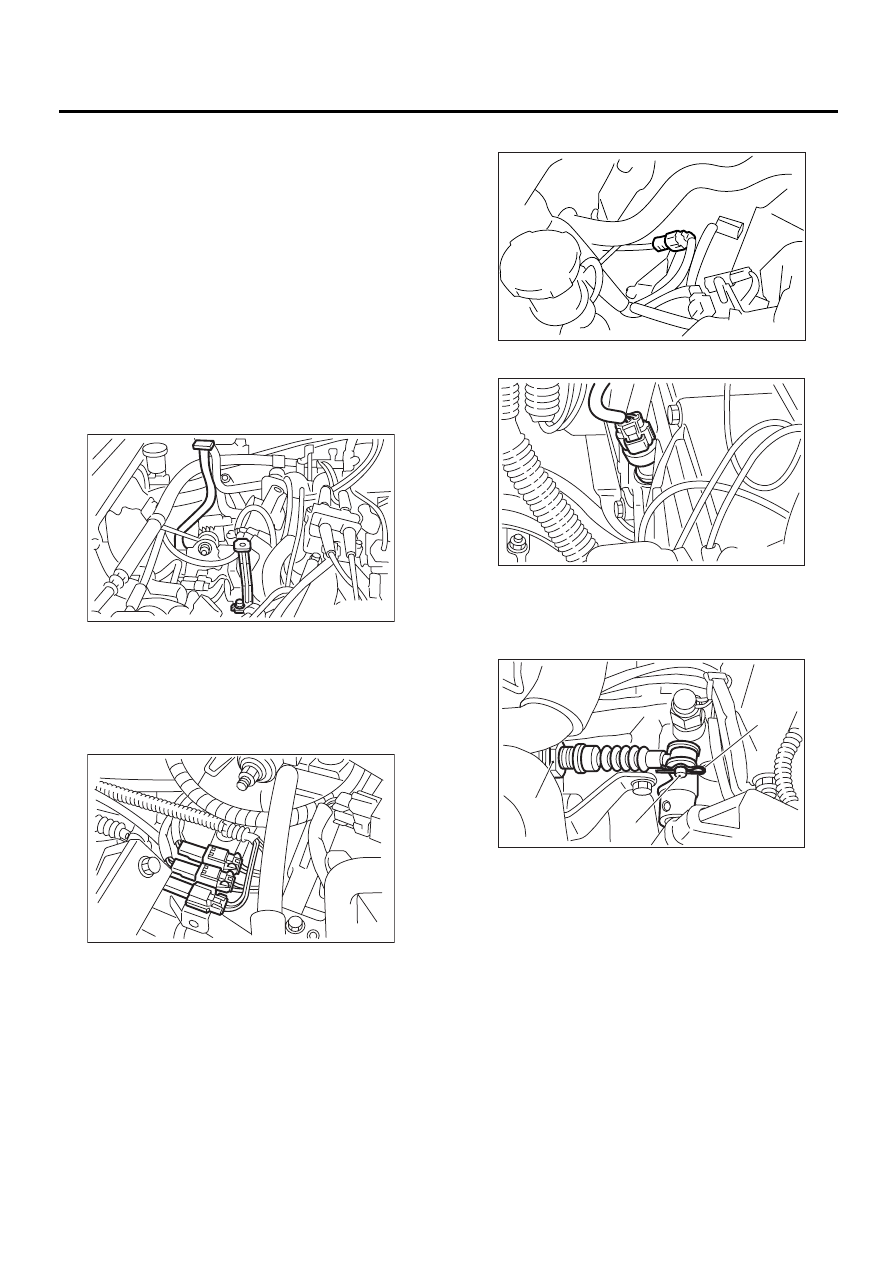
8) Disconnect the following connectors.
(1) Neutral position switch connector
(2) Back-up light switch connector
(3) High-low switch connector (Dual-range
model)
Non-TURBO model
TURBO model
(4) Vehicle speed sensor
9) Remove snap pin and pin from the drive select
cable.
10) Remove the drive select cable on the transmis-
sion. (Dual-range model)
11) Remove starter.
Non-TURBO model
<Ref. to SC(H4SO)-6, REMOVAL, Starter.>
TURBO model
<Ref. to SC(H4DOSTC)-6, REMOVAL, Starter.>
MT-00062
MT-00063
(A) Snap pin
(B) Pin
(C) Drive select cable
MT-00382
MT-00065
( A )
( B )
( C )
MT-00066
MT-33
MANUAL TRANSMISSION AND DIFFERENTIAL
MANUAL TRANSMISSION ASSEMBLY
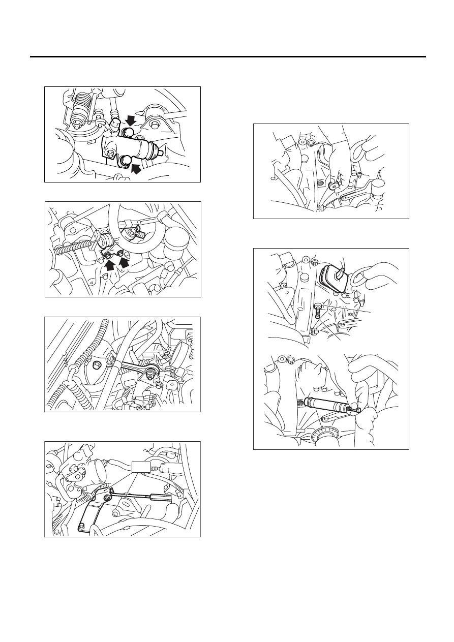
12) Remove operating cylinder from transmission.
Non-TURBO model
TURBO model
13) Remove pitching stopper.
14) Set ST.
ST
41099AA000
ENGINE SUPPORT ASSY
15) Separate the clutch release fork from release
bearing. (TURBO model)
(1) Remove the clutch operating cylinder from
transmission.
(2) Remove the plug using 10 mm hexagon
wrench.
(3) Screw the 6 mm dia. bolt into the release
fork shaft, and remove it.
(4) Raise the release fork and unfasten the re-
lease bearing tabs to free release fork.
NOTE:
Step (4) is required to prevent interference with the
engine when removing the engine from transmis-
sion.
MT-00067
MT-00068
MT-00354
MT-00070
ST
(A) Shaft
(B) Bolt
MT-00071
MT-00072
( A )
( B )
MT-34
MANUAL TRANSMISSION AND DIFFERENTIAL
MANUAL TRANSMISSION ASSEMBLY
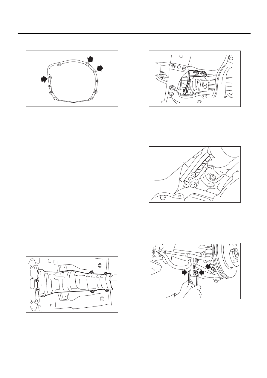
16) Remove bolt which holds right upper side of
transmission to engine.
17) Remove under cover.
18) Remove front and center exhaust pipes. (Non-
TURBO model)
Without OBD
<Ref. to EX(H4SOw/oOBD)-9, REMOVAL, Front
Exhaust Pipe.>
With OBD
<Ref. to EX(H4SO)-5, REMOVAL, Front Exhaust
Pipe.>
19) Remove center exhaust pipe. (TURBO model)
<Ref. to EX(H4DOSTC)-7, REMOVAL, Center Ex-
haust Pipe.>
20) Remove rear exhaust pipe and muffler.
Non-TURBO model without OBD
<Ref. to EX(H4SOw/oOBD)-13, REMOVAL, Rear
Exhaust Pipe.> and <Ref. to EX(H4SOw/oOBD)-
14, REMOVAL, Muffler.>
Non-TURBO with OBD
<Ref. to EX(H4SO)-9, REMOVAL, Rear Exhaust
Pipe.> and <Ref. to EX(H4SO)-10, REMOVAL,
Muffler.>
TURBO model
<Ref. to EX(H4DOSTC)-12, REMOVAL, Rear Ex-
haust Pipe.> and <Ref. to EX(H4DOSTC)-13, RE-
MOVAL, Muffler.>
21) Remove heat shield cover. (If equipped)
22) Remove hanger bracket from right side of
transmission.
23) Remove propeller shaft. <Ref. to DS-14, RE-
MOVAL, Propeller Shaft.>
24) Remove gear shift rod and stay from transmis-
sion.
(1) Disconnect stay from transmission.
(2) Disconnect rod from transmission.
25) Disconnect stabilizer link from transverse link.
26) Remove bolt securing ball joint of transverse
link to housing.
MT-00073
MT-00355
(A) Stay
(B) Rod
MT-00074
MT-00075
( A )
( B )
MT-00356
MT-35
MANUAL TRANSMISSION AND DIFFERENTIAL
MANUAL TRANSMISSION ASSEMBLY
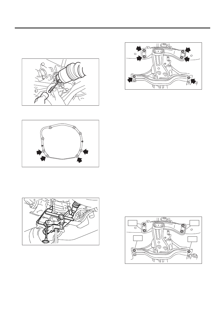
27) Remove spring pins and separate front drive
shafts from each side of the transmission.
NOTE:
Discard removing spring pin. Replace with a new
one.
28) Remove nuts which hold lower side of trans-
mission to engine.
29) Place transmission jack under transmission.
CAUTION:
• Always support transmission case with a
transmission jack.
• Fix transmission with a band etc.
30) Remove transmission rear crossmember from
vehicle.
31) Move transmission jack toward rear until main
shaft is withdrawn from clutch cover.
32) Separate transmission assembly and rear
cushion rubber.
B: INSTALLATION
1) Install clutch release bearing and lever to trans-
mission. (TURBO model)
<Ref. to CL-22, INSTALLATION, Release Bearing
and Lever.>
2) Install rear cushion rubber to transmission as-
sembly.
Tightening torque:
35 N·m (3.6 kgf-m, 26 ft-lb)
3) Install transmission onto engine.
(1) Gradually raise transmission with transmis-
sion jack.
(2) Engage them at splines.
NOTE:
Be careful not to strike main shaft against clutch
cover.
4) Install transmission rear crossmember.
Tightening torque:
T1: 70 N·m (7.1 kgf-m, 51 ft-lb)
T2: 140 N·m (14.3 kgf-m, 103 ft-lb)
5) Take off transmission jack.
MT-00357
MT-00077
MT-00078
MT-00079
MT-00081
T1
T1
T2
T2
Нет комментариевНе стесняйтесь поделиться с нами вашим ценным мнением.
Текст