Subaru Legacy III (2000-2003 year). Service manual — part 863
AC-40
HVAC SYSTEM (HEATER, VENTILATOR AND A/C)
INTAKE UNIT
15.Intake Unit
A: REMOVAL
1) Using refrigerant recovery system, discharge re-
frigerant. <Ref. to AC-23, OPERATION, Refriger-
ant Recovery Procedure.>
2) Disconnect ground cable from battery.
3) Remove bolts securing expansion valve and
pipe in engine compartment.
4) Remove instrument panel. <Ref. to EI-35, RE-
MOVAL, Instrument Panel Assembly.>
5) Remove keyless unit and CRU unit.
6) Disconnect sunroof connector.
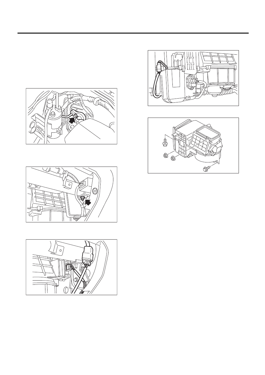
7) Disconnect servo motor connector.
8) Disconnect heater blower power transistor con-
nector.
9) Disconnect heater blower motor connector.
10) Disconnect in-vehicle temperature sensor con-
nector.
11) Remove bolts and nuts on the unit.
12) Disconnect drain hose.
13) Remove the unit.
B: INSTALLATION
1) Install in the reverse order of removal.
CAUTION:
Replace O-rings with new ones, and apply com-
pressor oil.
2) Charge refrigerant. <Ref. to AC-24, OPERA-
TION, Refrigerant Charging Procedure.>
AC-00297
AC-00277
AC-00278
AC-00298
AC-00299
AC-41
HVAC SYSTEM (HEATER, VENTILATOR AND A/C)
INTAKE UNIT
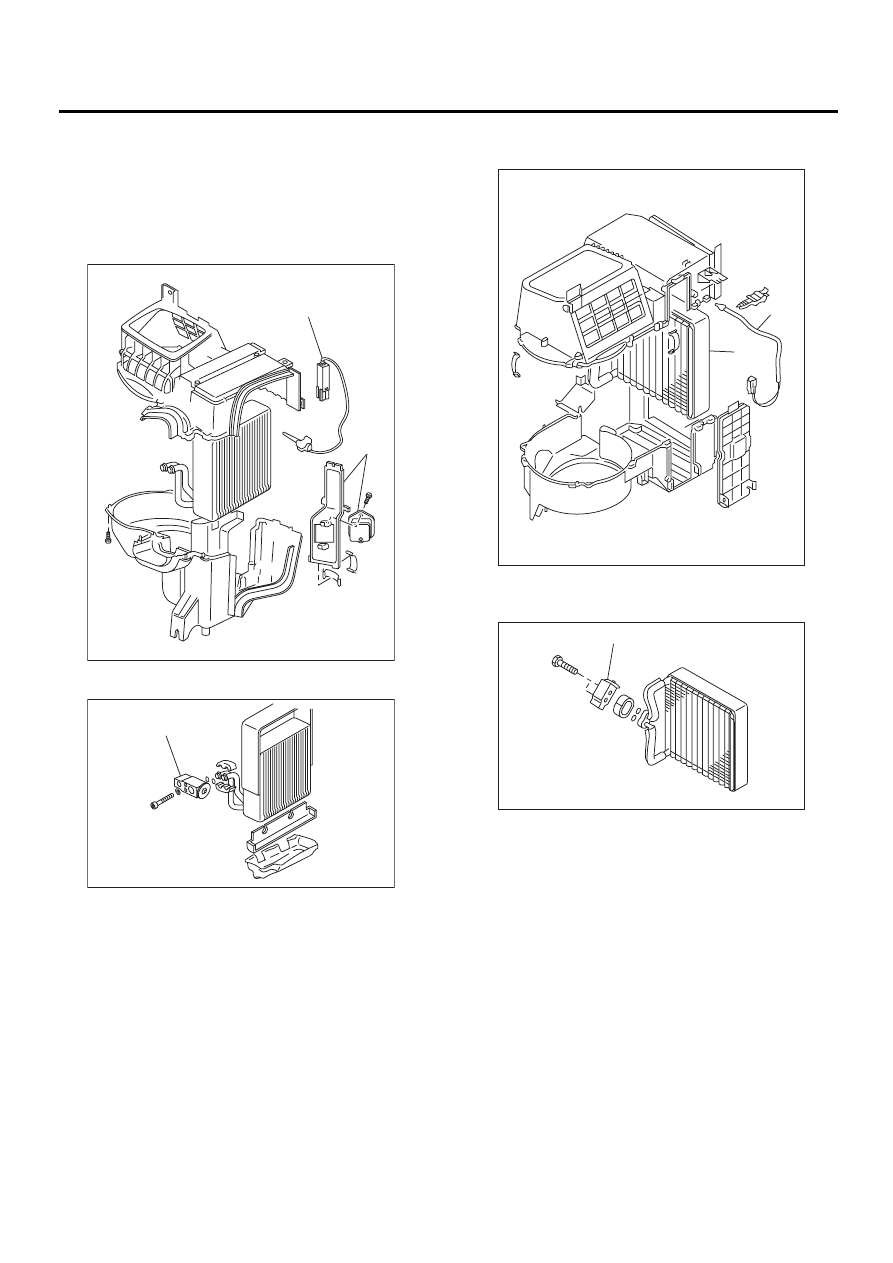
C: DISASSEMBLY
1. LHD MODEL
1) Remove resistor (A) and thermistor (B) from in-
take unit case.
2) Remove screws and clips to separate intake
unit.
3) Remove expansion valve (A) from evaporator.
2. RHD MODEL
1) Remove some screws and clips, then separate
intake unit case.
2) Remove thermostat (A) and then detach evapo-
rator (B).
3) Remove the block expansion valve (A) from
evaporator.
CAUTION:
If evaporator is replaced, add appropriate
amount of compressor oil to evaporator. <Ref.
to AC-29, REPLACEMENT, Compressor Oil.>
D: ASSEMBLY
Assemble in the reverse order of disassembly.
CAUTION:
Replace O-rings with new ones, and then apply
compressor oil.
AC-00300
( A )
( B )
AC-00301
( A )
AC-00467
( A )
( B )
AC-00468
( A )
AC-42
HVAC SYSTEM (HEATER, VENTILATOR AND A/C)
FLEXIBLE HOSE
16.Flexible Hose
A: REMOVAL
CAUTION:
• When disconnecting/connecting hoses, do
not apply excessive force them. Confirm that
no torsion and excessive tension exist after in-
stalling.
• Seal the disconnected hose with a plug or vi-
nyl tape to prevent contamination from enter-
ing.
1) Disconnect ground cable from battery.
2) Using refrigerant recovery system, discharge re-
frigerant. <Ref. to AC-23, OPERATION, Refriger-
ant Recovery Procedure.>
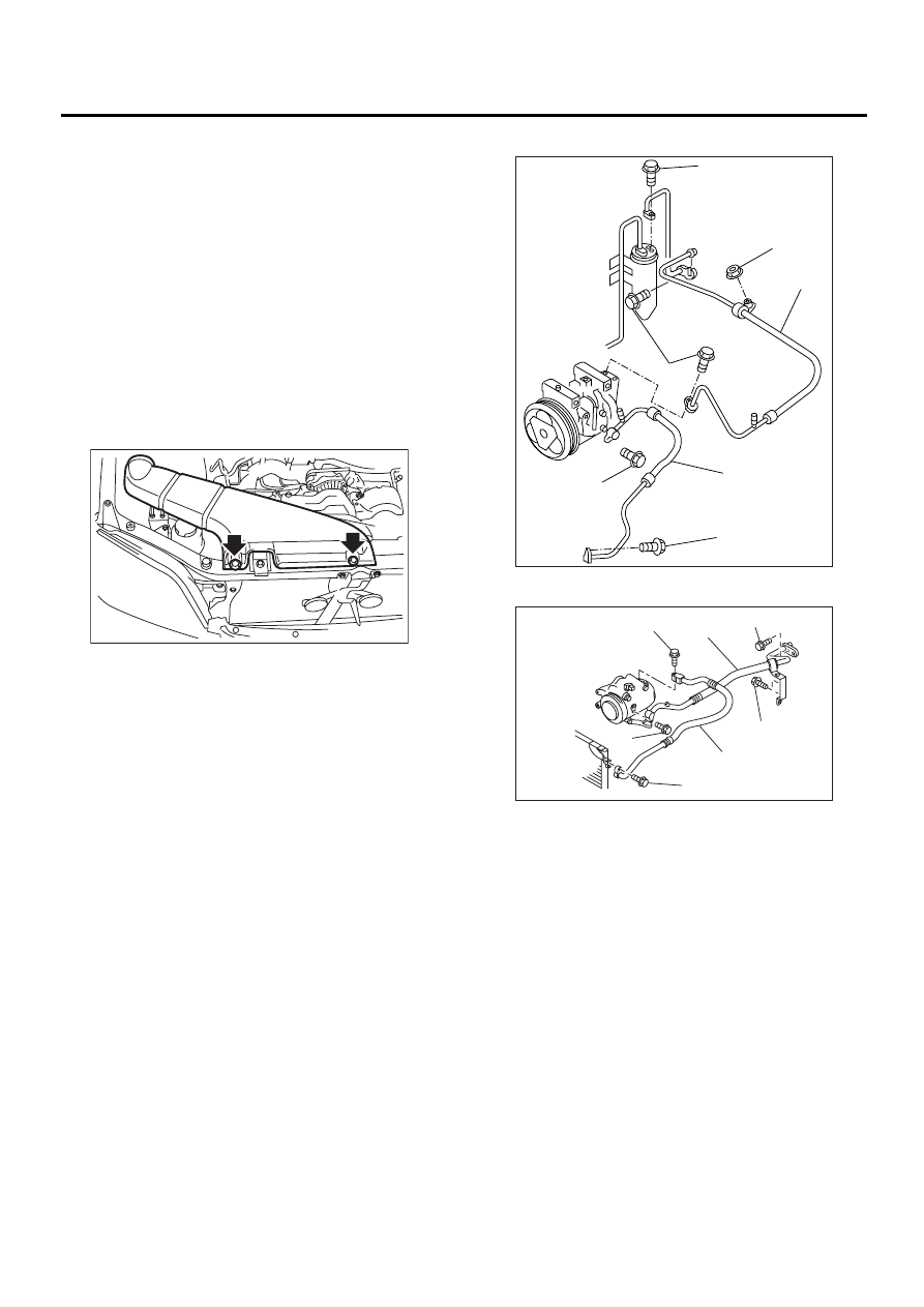
3) Remove duct (A).
4) Remove hose attaching bolts (C).
5) Disconnect hose from evaporator unit.
6) Disconnect hose from compressor.
7) Remove low-pressure hose (A) from the vehicle.
8) Remove hose attaching bolts (D).
9) Disconnect hose from compressor.
10) Disconnect hose from condenser.
11) Disconnect high-pressure hose (B) from the ve-
hicle.
・
・
・
・
LHD model
・
・
・
・
RHD model
B: INSTALLATION
CAUTION:
When disconnecting/connecting hoses, do not
apply an excessive force them. Confirm that no
torsion and excessive tension exist after in-
stalling. Seal the disconnected hose with a plug
or vinyl tape to prevent contamination from en-
tering.
1) Install in the reverse order of removal.
2) Charge refrigerant. <Ref. to AC-24, OPERA-
TION, Refrigerant Charging Procedure.>
C: INSPECTION
NOTE:
If cracking, damage, or swelling is found on a hose,
replace it with a new one.
AC-00289
( A )
AC-00302
( A )
( B )
( C )
( C )
( C )
( D )
( D )
AC-00469
( D )
( D )
( C )
( C )
( C )
( B )
( A )
AC-43
HVAC SYSTEM (HEATER, VENTILATOR AND A/C)
RELAY AND FUSE
17.Relay and Fuse
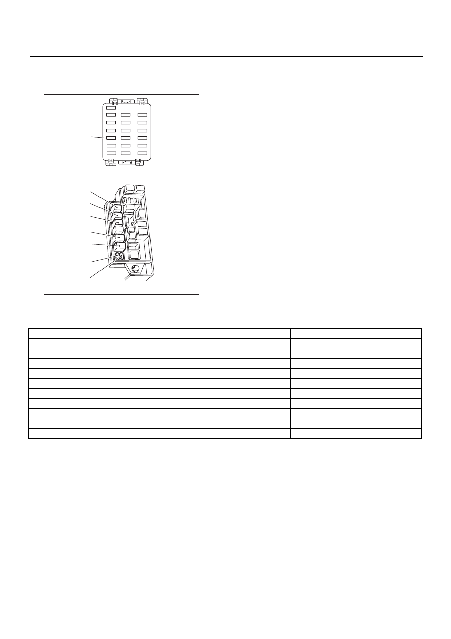
A: LOCATION
(1) Joint box
(2) Main fuse box
AC-00303
( C )
( H )
( G )
( B )
( D )
( E )
( F )
( A )
( 1 )
( 2 )
4 cylinder engine model
6 cylinder engine model
Main fan relay
F
—
Sub fan relay
B
—
A/C relay
A
A
Main fan relay 1
—
F
Sub fan relay 1
—
G
Main fan relay 2
—
B
Sub fan relay 2
—
H
A/C fuse
C
C
Main fan fuse
E (20 A)
E (30 A)
Sub fan fuse
D (20 A)
D (30 A)
Нет комментариевНе стесняйтесь поделиться с нами вашим ценным мнением.
Текст