Subaru Legacy III (2000-2003 year). Service manual — part 861
AC-32
HVAC SYSTEM (HEATER, VENTILATOR AND A/C)
HEATER BLOWER RESISTOR
9. Heater Blower Resistor
A: REMOVAL
1) Remove glove box. <Ref. to EI-32, REMOVAL,
Glove Box.>
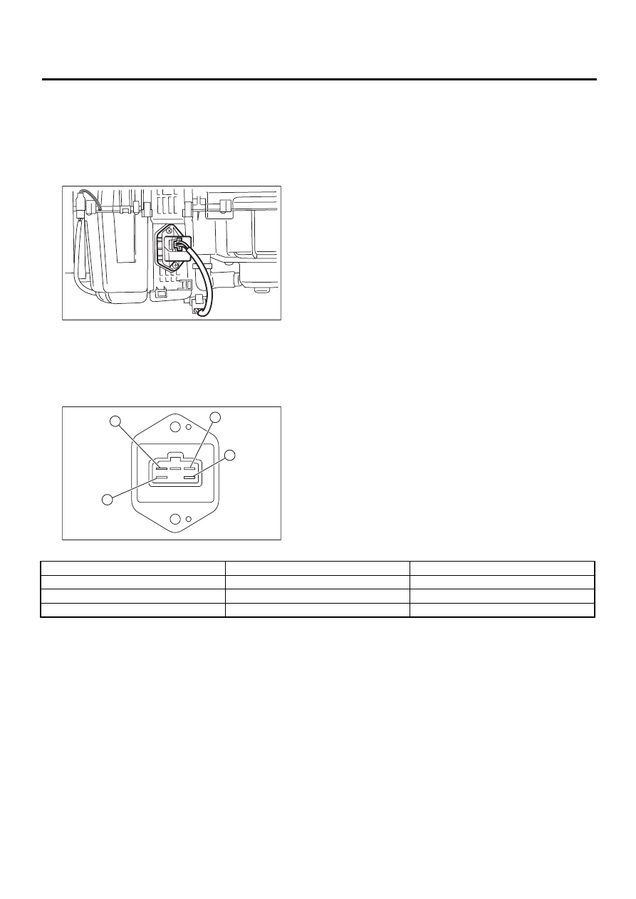
2) Disconnect power transistor connector.
3) Loosen 2 screws to remove power transistor.
B: INSTALLATION
Install in the reverse order of removal.
C: INSPECTION
1. MANUAL A/C
Measure switch resistance.
If NG, replace the blower resistor.
AC-00282
AC-00283
4
3
2
1
Terminal No.
Condition
Standard
4 and 3
Constant
Approx. 0.46
Ω
3 and 2
Constant
Approx. 0.85
Ω
2 and 1
Constant
Approx. 1.77
Ω
AC-33
HVAC SYSTEM (HEATER, VENTILATOR AND A/C)
HEATER CORE
10.Heater Core
A: REMOVAL
1) Remove heater unit. <Ref. to AC-30, REMOV-
AL, Heater Unit.>
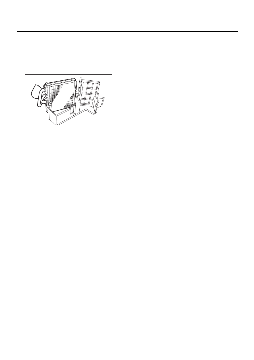
2) Remove screws to separate heater unit case.
3) Remove heater core.
B: INSTALLATION
Install in the reverse order of removal.
AC-00284
AC-34
HVAC SYSTEM (HEATER, VENTILATOR AND A/C)
CONTROL UNIT
11.Control Unit
A: REMOVAL
1. AUTO A/C
1) Disconnect ground cable from battery.
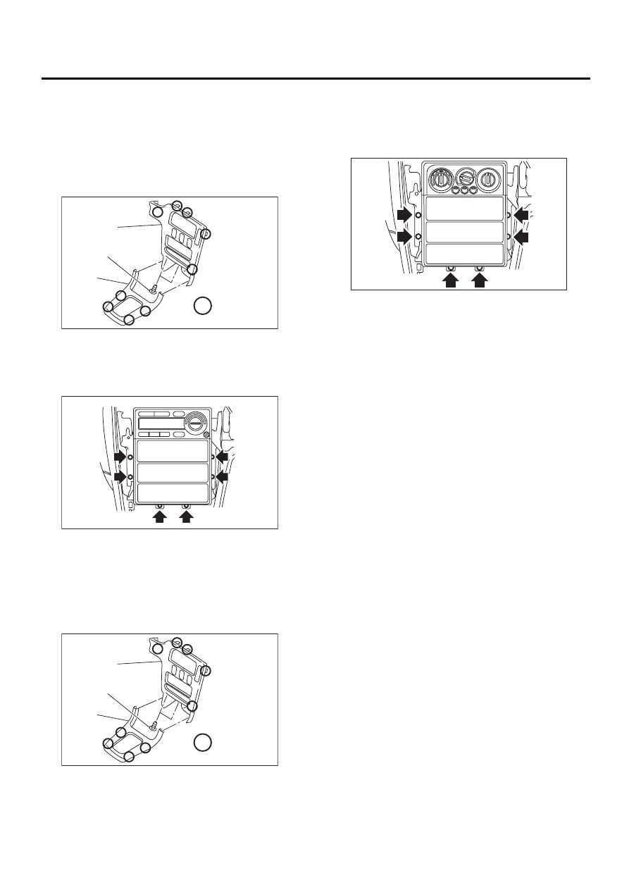
2) Remove front cover (A).
3) Loosen 2 screws (B) to remove center panel (C).
4) Loosen screws to pull control unit slightly out of
center console.
5) Disconnect connector from antenna cable to re-
move control unit.
2. MANUAL A/C
1) Disconnect ground cable from battery.
2) Remove front cover (A).
3) Loosen 2 screws (B) to remove center panel (C).
4) Set temperature control switch to “FULL HOT”,
and disconnect temperature control cable from
heater unit.
5) Loosen screws to pull control unit slightly out of
center console.
6) Disconnect connector from antenna cable to re-
move control unit.
B: INSTALLATION
1. AUTO A/C
Install in the reverse order of removal.
2. MANUAL A/C
1) Install in the reverse order of removal.
2) Before installation, set temperature control
switch to “FULL HOT”.
(A) Hook pawl
(A) Hook pawl
AC-00285
:
( A )
( B )
( C )
( 1 )
AC-00286
AC-00285
:
( A )
( B )
( C )
( 1 )
AC-00287
AC-35
HVAC SYSTEM (HEATER, VENTILATOR AND A/C)
COMPRESSOR
12.Compressor
A: INSPECTION
1. MAGNETIC CLUTCH CLEARANCE
1) Check the clearance of the entire circumference
around the drive plate and pulley.
Standard:
0.45
±±±±
0.15 mm (0.0177
±±±±
0.0059 in)
2. MAGNETIC CLUTCH OPERATION
1) Disconnect the compressor connector.
2) Connect the No. 3 terminal of the compressor
connector from the battery to the positive (+) lead.
Ground the negative (
−
) lead to the body.
3) Make sure the magnet clutch engages.
If NG, replace the compressor.
B: REMOVAL
1) Perform oil return operation. <Ref. to AC-29,
OPERATION, Compressor Oil.>
2) Turn A/C switch OFF and stop the engine.
3) Using refrigerant recovery system, discharge re-
frigerant. <Ref. to AC-23, OPERATION, Refriger-
ant Recovery Procedure.>
4) Disconnect ground cable from battery.
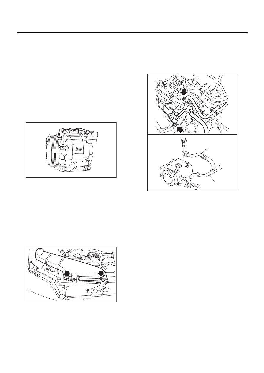
5) Remove duct (A).
6) Disconnect low-pressure hose (A) and high-
pressure hose (B).
CAUTION:
Be careful not to lose O-rings on hose. Immedi-
ately seal hose with a plug or vinyl tape to pre-
vent the entry of contamination.
7) Remove V-belt.
H4 model <Ref. to ME(H4SO)-41, REMOVAL, V-
belt.>
H4 model <Ref. to ME(H6DO)-28, REMOVAL, V-
belt.>
8) Remove generator.
H4 non-TURBO model <Ref. to SC(H4SO)-14, RE-
MOVAL, Generator.>
H4 TURBO model <Ref. to SC(H4DOSTC)-14, RE-
MOVAL, Generator.>
H6 model <Ref. to SC(H6DO)-14, REMOVAL,
Generator.>
9) Disconnect compressor harness from body har-
ness.
10) Remove bolts from compressor bracket.
AC-00288
AC-00289
( A )
(1) LHD model
(2) RHD model
AC-00465
( A )
( A )
( B )
( B )
( 1 )
( 2 )
Нет комментариевНе стесняйтесь поделиться с нами вашим ценным мнением.
Текст