Subaru Legacy III (2000-2003 year). Service manual — part 60
ME(H4SO)-52
MECHANICAL
CAMSHAFT SPROCKET
6) Install the crankshaft pulley. <Ref. to
ME(H4SO)-43, INSTALLATION, CRANKSHAFT
PULLEY.>
7) Install the V-belt. <Ref. to ME(H4SO)-42, IN-
STALLATION, V-belt.>
C: INSPECTION
1) Check the sprocket teeth for abnormal wear and
scratches.
2) Make sure there is no free play between sprock-
et and key.
3) Check the crankshaft sprocket notch for sensor
for damage and contamination of foreign matter.
ME(H4SO)-53
MECHANICAL
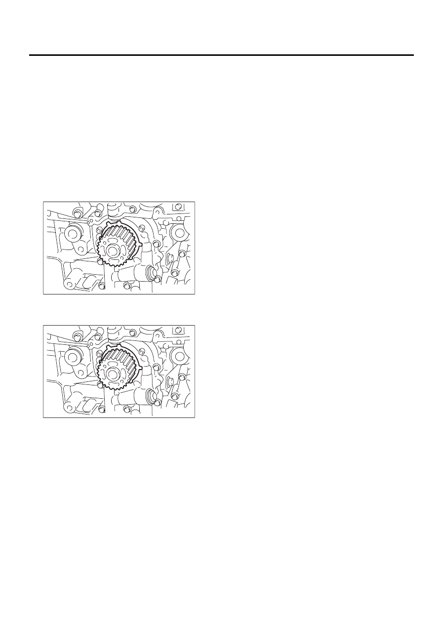
CRANKSHAFT SPROCKET
17.Crankshaft Sprocket
A: REMOVAL
1) Remove the V-belt. <Ref. to ME(H4SO)-41, RE-
MOVAL, V-belt.>
2) Remove the crankshaft pulley. <Ref. to
ME(H4SO)-43, REMOVAL, Crankshaft Pulley.>
3) Remove the belt cover. <Ref. to ME(H4SO)-45,
REMOVAL, Belt Cover.>
4) Remove the timing belt assembly. <Ref. to
ME(H4SO)-46, REMOVAL, Timing Belt Assem-
bly.>
5) Remove the camshaft sprocket. <Ref. to
ME(H4SO)-51, REMOVAL, Camshaft Sprocket.>
6) Remove the crankshaft sprocket.
B: INSTALLATION
1) Install the crankshaft sprocket.
2) Install the camshaft sprocket. <Ref. to
ME(H4SO)-51, INSTALLATION, Camshaft
Sprocket.>
3) Install the timing belt assembly. <Ref. to
ME(H4SO)-47, INSTALLATION, Timing Belt As-
sembly.>
4) Install the belt cover. <Ref. to ME(H4SO)-45, IN-
STALLATION, Belt Cover.>
5) Install the crankshaft pulley. <Ref. to
ME(H4SO)-43, INSTALLATION, CRANKSHAFT
PULLEY.>
6) Install the V-belt. <Ref. to ME(H4SO)-42, IN-
STALLATION, V-belt.>
C: INSPECTION
1) Check the sprocket teeth for abnormal wear and
scratches.
2) Make sure there is no free play between sprock-
et and key.
3) Check the crankshaft sprocket notch for sensor
for damage and contamination of foreign matter.
ME-00252
ME-00252
ME(H4SO)-54
MECHANICAL
VALVE ROCKER ASSEMBLY
18.Valve Rocker Assembly
A: REMOVAL
1) Remove the V-belt. <Ref. to ME(H4SO)-41, RE-
MOVAL, V-belt.>
2) Remove the crankshaft pulley. <Ref. to
ME(H4SO)-43, REMOVAL, Crankshaft Pulley.>
3) Remove the belt cover. <Ref. to ME(H4SO)-45,
REMOVAL, Belt Cover.>
4) Remove the timing belt assembly. <Ref. to
ME(H4SO)-46, REMOVAL, Timing Belt Assem-
bly.>
5) Remove the camshaft sprocket. <Ref. to
ME(H4SO)-51, REMOVAL, Camshaft Sprocket.>
6) Disconnect the PCV hose and remove rocker
cover.
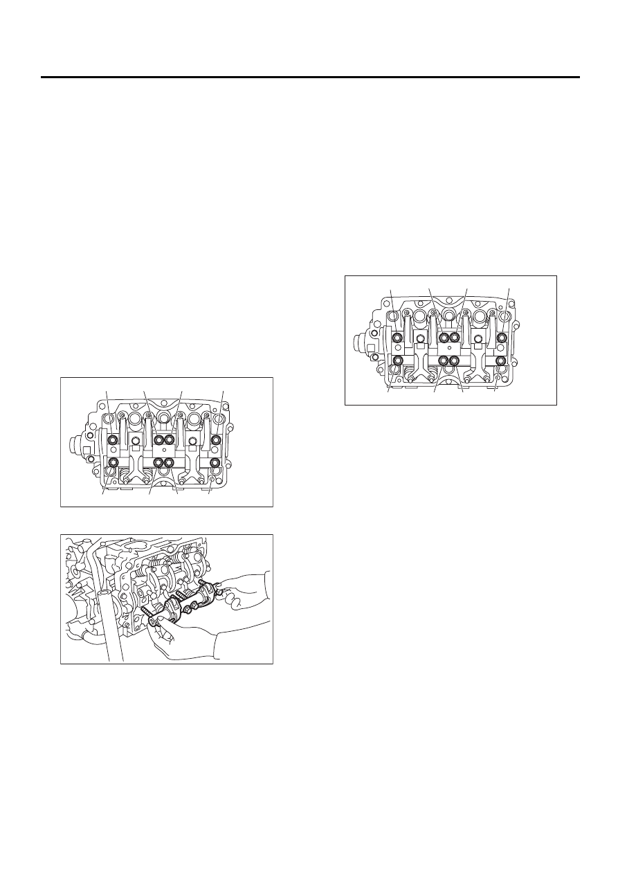
7) Removal of valve rocker assembly
(1) Remove the bolts (a) through (h) in alpha-
betical sequence.
NOTE:
Leave two or three threads of bolts (g and h) en-
gaged to retain the valve rocker assembly.
(2) Remove the valve rocker assembly.
B: INSTALLATION
1) Installation of valve rocker assembly
(1) Temporarily tighten the bolts (a) through (d)
equally as shown in the figure.
NOTE:
Do not allow the valve rocker assembly to gouge
knock pins.
(2) Tighten the bolts (e) through (h) to specified
torque.
(3) Tighten the bolts (a) through (d) to specified
torque.
Tightening torque:
25 N·m (2.5 kgf-m, 18.1 ft-lb)
2) Adjust the valve clearances. <Ref. to
ME(H4SO)-30, ADJUSTMENT, Valve Clearance.>
3) Install the rocker cover and connect PCV hose.
4) Install the camshaft sprocket. <Ref. to
ME(H4SO)-51, INSTALLATION, Camshaft
Sprocket.>
5) Install the timing belt assembly. <Ref. to
ME(H4SO)-47, INSTALLATION, Timing Belt As-
sembly.>
6) Install the belt cover. <Ref. to ME(H4SO)-45, IN-
STALLATION, Belt Cover.>
7) Install the crankshaft pulley. <Ref. to
ME(H4SO)-43, INSTALLATION, CRANKSHAFT
PULLEY.>
8) Install the V-belt. <Ref. to ME(H4SO)-42, IN-
STALLATION, V-belt.>
C: DISASSEMBLY
1) Remove the bolts which secure rocker shaft.
2) Extract the rocker shaft. Remove the valve rock-
er arms, springs, plates and shaft supports from
rocker shaft.
NOTE:
Arrange all removed parts in order so that they can
be installed in their original positions.
3) Remove the nut and adjuster screw from valve
rocker.
ME-00253
( a )
( b )
( c )
( d )
( e )
( g )
( h )
( f )
ME-00254
ME-00255
( a )
( b )
( c )
( d )
( e )
( g )
( h )
( f )
ME(H4SO)-55
MECHANICAL
VALVE ROCKER ASSEMBLY
D: ASSEMBLY
1) Install the adjuster screw and nut to valve rocker.
2) Arrange the valve rocker arms, springs and shaft
supports in assembly order and insert valve rocker
shaft.
Tightening torque (Shaft supports installing
bolts):
5 N·m (0.5 kgf-m, 3.6 ft-lb)
NOTE:
Valve rocker arms, rocker shaft and shaft supports
have identification marks. Ensure the parts with
same markings are properly assembled.
3) Install the valve rocker shaft securing bolts.
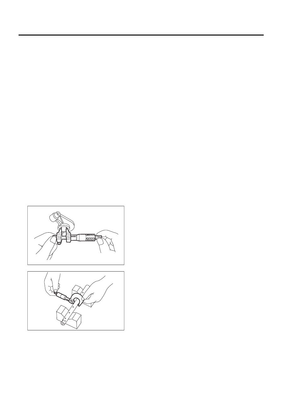
E: INSPECTION
1. VALVE ROCKER ARM AND ROCKER
SHAFT
1) Measure the inside diameter of valve rocker arm
and outside diameter of valve rocker shaft, and de-
termine the difference between the two (= oil clear-
ance).
Clearance between arm and shaft:
Standard
0.020 — 0.054 mm (0.0008 — 0.0021 in)
Limit
0.10 mm (0.0039 in)
2) If oil clearance exceeds the limit, replace the
valve rocker arm or shaft, whichever shows greater
amount of wear.
Rocker arm inside diameter:
22.020 — 22.041 mm (0.8669 — 0.8678 in)
Rocker shaft diameter:
21.987 — 22.000 mm (0.8656 — 0.8661 in)
3) If cam or valve contact surface of valve rocker
arm is worn or dented excessively, replace the
valve rocker arm.
4) Check that the valve rocker arm roller rotates
smoothly. If not, replace the valve rocker arm.
ME-00256
ME-00257
Нет комментариевНе стесняйтесь поделиться с нами вашим ценным мнением.
Текст