Subaru Legacy III (2000-2003 year). Service manual — part 61
ME(H4SO)-56
MECHANICAL
CAMSHAFT
19.Camshaft
A: REMOVAL
1) Remove the V-belt. <Ref. to ME(H4SO)-42, IN-
STALLATION, V-belt.>
2) Remove the crankshaft pulley. <Ref. to
ME(H4SO)-43, REMOVAL, Crankshaft Pulley.>
3) Remove the belt cover. <Ref. to ME(H4SO)-45,
REMOVAL, Belt Cover.>
4) Remove the timing belt assembly. <Ref. to
ME(H4SO)-46, REMOVAL, Timing Belt Assem-
bly.>
5) Remove the camshaft sprocket. <Ref. to
ME(H4SO)-51, REMOVAL, Camshaft Sprocket.>
6) Remove the crankshaft sprocket. <Ref. to
ME(H4SO)-53, REMOVAL, Crankshaft Sprocket.>
7) Remove the belt cover No. 2 (LH).
8) Remove the belt cover No. 2 (RH).
NOTE:
Do not damage or lose the seal rubber when re-
moving belt covers.
9) Remove the tensioner bracket.
10) Remove the camshaft position sensor support.
(LH side only)
11) Remove the oil level gauge guide. (LH side
only)
12) Remove the valve rocker assembly. <Ref. to
ME(H4SO)-54, REMOVAL, Valve Rocker Assem-
bly.>
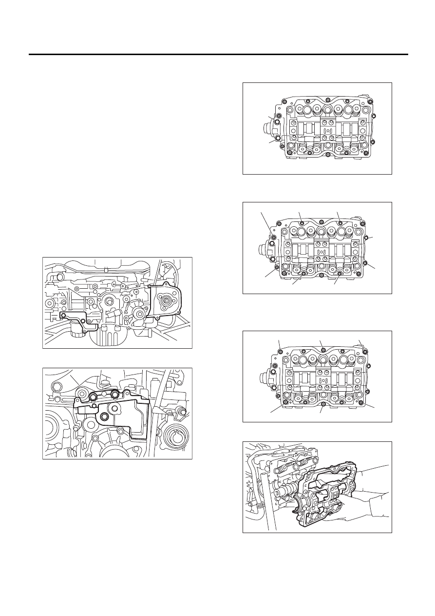
13) Remove the camshaft cap.
(1) Remove the bolts (a) through (b) in alpha-
betical sequence.
(2) Equally loosen the bolts (c) through (j) all the
way in alphabetical sequence.
(3) Remove the bolts (k) through (p) in alpha-
betical sequence using ST.
ST
499497000
TORX PLUS
(4) Remove the camshaft cap.
14) Remove the camshaft.
15) Remove the oil seal.
ME-00258
ME-00259
ME-00260
( a )
( b )
ME-00261
( c )
( d )
( e )
( g )
( h )
( i )
( j )
( f )
ME-00262
( k )
( n )
( o )
( p )
( m )
( l )
ME-00263
ME(H4SO)-57
MECHANICAL
CAMSHAFT
16) Remove the plug from rear side of camshaft.
NOTE:
• Do not remove the oil seal unless necessary.
• Do not scratch the journal surface when remov-
ing oil seal.
B: INSTALLATION
1) Apply a coat of engine oil to the camshaft jour-
nals, and then install the camshaft.
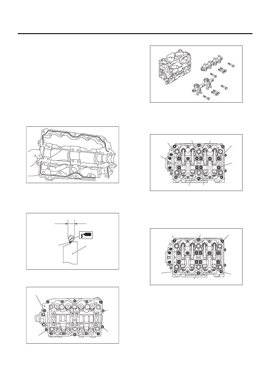
2) Install the camshaft cap.
(1) Apply liquid gasket on the around of cam-
shaft cap.
Liquid gasket:
THREE BOND 1280B
P/N
K0877YA018
NOTE:
Apply a coat of 3 mm (0.12 in) dia (A). liquid gasket
along edge (B) of the camshaft cap (C) mating sur-
face.
(2) Temporarily tighten the bolts (g) through (j)
in alphabetical sequence.
(3) Install the valve rocker assembly.
(4) Tighten the bolts (a) through (h) in alphabet-
ical sequence.
Tightening torque:
25 N·m (2.5 kgf-m, 18.1 ft-lb)
(5) Tighten the TORX bolts (i) through (n) in al-
phabetical sequence using ST.
ST
499497000
TORX PLUS
Tightening torque:
18 N·m (1.8 kgf-m, 13.0 ft-lb)
ME-00264
( A )
( B )
( C )
ME-00265
ME-00266
( g )
( h )
( i )
( j )
ME-00267
ME-00268
( a )
( b )
( c )
( d )
( e )
( g )
( h )
( f )
ME-00269
( k )
( n )
( m )
( l )
( i )
( j )
ME(H4SO)-58
MECHANICAL
CAMSHAFT
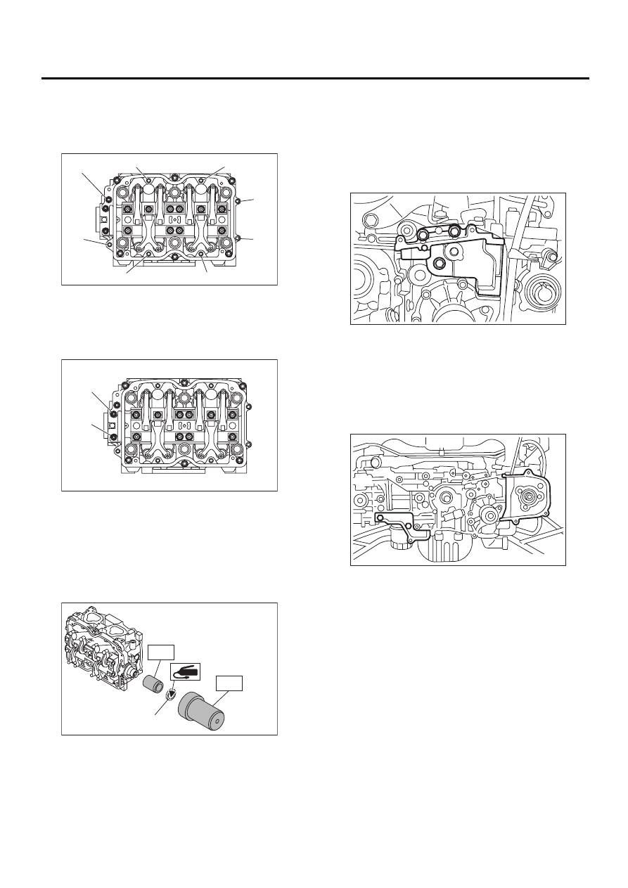
(6) Tighten the bolts (o) through (v) in alphabet-
ical sequence.
Tightening torque:
10 N·m (1.0 kgf-m, 7.2 ft-lb)
(7) Tighten the bolts (w) through (x) in alphabet-
ical sequence.
Tightening torque:
10 N·m (1.0 kgf-m, 7.2 ft-lb)
3) Apply a coat of grease to oil seal lips, and then
install the oil seal (A) on camshaft using ST1 and
ST2.
NOTE:
Use a new oil seal.
ST1
499597000
OIL SEAL GUIDE
ST2
499587500
OIL SEAL INSTALLER
4) Install the plug using ST.
ST
499587700
CAMSHAFT OIL SEAL IN-
STALLER
5) Adjust the valve clearance. <Ref. to ME(H4SO)-
30, ADJUSTMENT, Valve Clearance.>
6) Install the rocker cover and connect PCV hose.
7) Install the oil level gauge guide. (LH side only)
8) Install the camshaft position sensor support. (LH
side only)
9) Install the tensioner bracket.
Tightening torque:
25 N·m (2.5 kgf-m, 18.1 ft-lb)
10) Install the belt cover No. 2 (RH).
Tightening torque:
5 N·m (0.5 kgf-m, 3.6 ft-lb)
11) Install the belt cover No. 2 (LH).
Tightening torque:
5 N·m (0.5 kgf-m, 3.6 ft-lb)
12) Install the crankshaft sprocket. <Ref. to
ME(H4SO)-53, INSTALLATION, Crankshaft
Sprocket.>
13) Install the camshaft sprocket. <Ref. to
ME(H4SO)-51, INSTALLATION, Camshaft
Sprocket.>
14) Install the timing belt assembly. <Ref. to
ME(H4SO)-47, INSTALLATION, Timing Belt As-
sembly.>
15) Install the belt cover. <Ref. to ME(H4SO)-45,
INSTALLATION, Belt Cover.>
16) Install the crankshaft pulley. <Ref. to
ME(H4SO)-43, INSTALLATION, CRANKSHAFT
PULLEY.>
17) Install the V-belt. <Ref. to ME(H4SO)-42, IN-
STALLATION, V-belt.>
ME-00270
( o )
( p )
( u )
( v )
( q )
( r )
( s )
( t )
ME-00271
( x )
( w )
ME-00272
ST1
ST2
( A )
ME-00273
ME-00274
ME(H4SO)-59
MECHANICAL
CAMSHAFT
C: INSPECTION
1. CAMSHAFT
1) Measure the bend, and repair or replace if nec-
essary.
Limit:
0.025 mm (0.0010 in)
2) Check the journal for damage and wear. Re-
place if faulty.
3) Measure the outside diameter of camshaft jour-
nal and inside diameter of cylinder head journal,
and determine the difference between two (= oil
clearance). If the oil clearance exceeds specifica-
tions, replace the camshaft or cylinder head as
necessary.
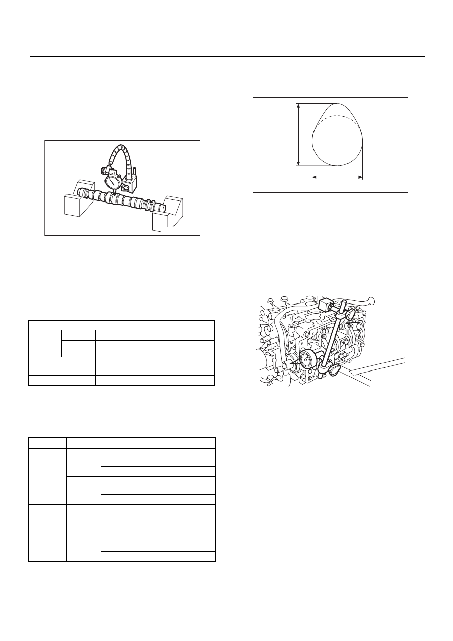
4) Check the cam face condition; remove the minor
faults by grinding with oil stone. Measure the cam
height H; replace if the limit has been exceeded.
Cam height: H
Cam base circle diameter A:
IN: 34.00 mm (1.3386 in)
EX: 34.00 mm (1.3386 in)
2. CAMSHAFT SUPPORT
Measure the thrust clearance of camshaft with dial
gauge. If the clearance exceeds the limit, replace
the camshaft support.
Standard:
0.030 — 0.090 mm (0.0012 — 0.0035 in)
Limit:
0.10 mm (0.0039 in)
Unit: mm (in)
Clear-
ance at
journal
Standard
0.055 — 0.090 (0.0022 — 0.0035)
Limit
0.10 (0.0039)
Camshaft journal
O.D.
31.928 — 31.945 (1.2570 — 1.2577)
Journal hole I.D.
32.000 — 32.018 (1.2598 — 1.2605)
Model
Item
Unit: mm (in)
2000 cc
Intake
STD
38.732 — 38.832
(1.5249 — 1.528885)
Limit
38.632 (1.5209)
Exhaust
STD
39.257 — 39.357
(1.5455 — 1.5495)
Limit
39.157 (1.5416)
2500 cc
Intake
STD
39.485 — 39.585
(1.5545 — 1.5585)
Limit
39.385 (1.5506)
Exhaust
STD
39.257 — 39.357
(1.5455 — 1.5495)
Limit
39.157 (1.5416)
ME-00275
ME-00276
H
A
ME-00277
Нет комментариевНе стесняйтесь поделиться с нами вашим ценным мнением.
Текст