Subaru Legacy III (2000-2003 year). Service manual — part 58
ME(H4SO)-44
MECHANICAL
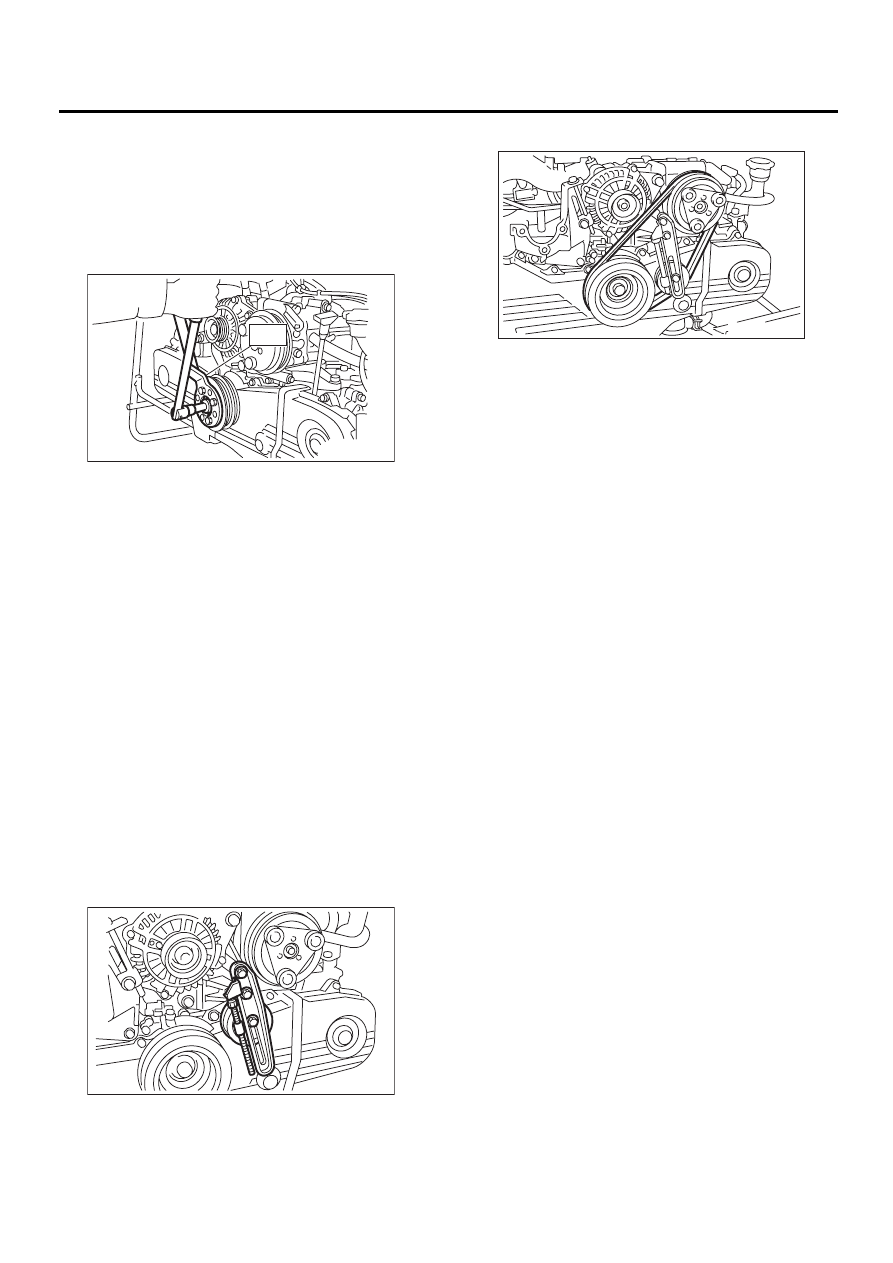
CRANKSHAFT PULLEY
(2) Apply engine oil to the crankshaft pulley bolt
seat and thread.
(3) Tighten the bolts temporarily with tightening
torque of 44 N·m (4.5 kgf-m, 33 ft-lb).
(4) Tighten the crankshaft pulley bolts.
Tightening torque:
177 N·m (18.0 kgf-m, 130.2 ft-lb)
3) Confirm that the tightening angle of crankshaft
pulley bolt is 65 degrees or more. If the tightening
angle of crankshaft pulley bolt is less than 65 de-
grees, conduct the following procedures.
(1) Replace the crankshaft pulley bolts and
clean them.
Crankshaft pulley bolt:
12369AA011
(2) Clean the crankshaft thread using an air
gun.
(3) Apply engine oil to the crankshaft pulley bolt
seat and thread.
(4) Tighten the bolts temporarily with tightening
torque of 44 N·m (4.5 kgf-m, 33 ft-lb).
(5) Tighten the crankshaft pulley bolts keeping
them in an angle between 65 degrees and 75
degrees.
NOTE:
Conduct the tightening procedures by confirming
the turning angle of crankshaft pulley bolt referring
to the gauge indicated on belt cover.
4) Install the A/C belt tensioner.
5) Install the A/C belt.
C: INSPECTION
1) Make sure the V-belt is not worn or otherwise
damaged.
2) Check the tension of the belt. <Ref. to
ME(H4SO)-42, INSPECTION, V-belt.>
ME-00227
ST
ME-00225
ME-00228
ME(H4SO)-45
MECHANICAL
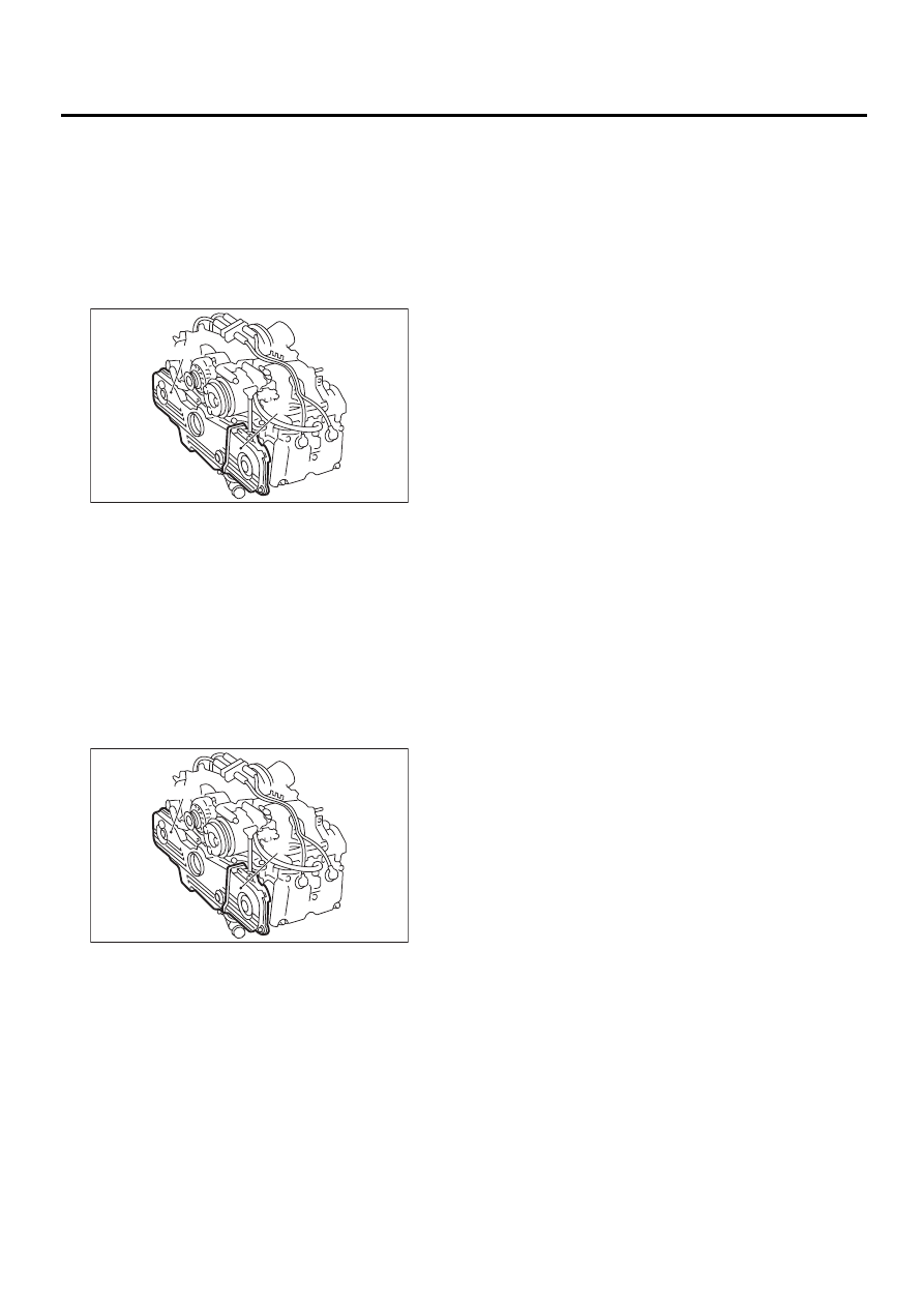
BELT COVER
14.Belt Cover
A: REMOVAL
1) Remove the V-belt. <Ref. to ME(H4SO)-41, RE-
MOVAL, V-belt.>
2) Remove the crankshaft pulley. <Ref. to
ME(H4SO)-43, REMOVAL, Crankshaft Pulley.>
3) Remove the belt cover (LH).
4) Remove the front belt cover.
B: INSTALLATION
1) Install the front belt cover.
Tightening torque:
5 N·m (0.5 kgf-m, 3.6 ft-lb)
2) Install the belt cover (LH).
Tightening torque:
5 N·m (0.5 kgf-m, 3.6 ft-lb)
3) Install the crankshaft pulley. <Ref. to
ME(H4SO)-43, INSTALLATION, CRANKSHAFT
PULLEY.>
4) Install the V-belt. <Ref. to ME(H4SO)-42, IN-
STALLATION, V-belt.>
C: INSPECTION
Make sure the cover is not damaged.
(A) Belt cover (LH)
(B) Front belt cover
(A) Belt cover (LH)
(B) Front belt cover
( A )
( B )
ME-00229
( A )
( B )
ME-00229
ME(H4SO)-46
MECHANICAL
TIMING BELT ASSEMBLY
15.Timing Belt Assembly
A: REMOVAL
1. TIMING BELT
1) Remove the V-belt. <Ref. to ME(H4SO)-41, RE-
MOVAL, V-belt.>
2) Remove the crankshaft pulley. <Ref. to
ME(H4SO)-43, REMOVAL, Crankshaft Pulley.>
3) Remove the belt cover. <Ref. to ME(H4SO)-45,
REMOVAL, Belt Cover.>
4) Remove the timing belt guide. (MT vehicles)
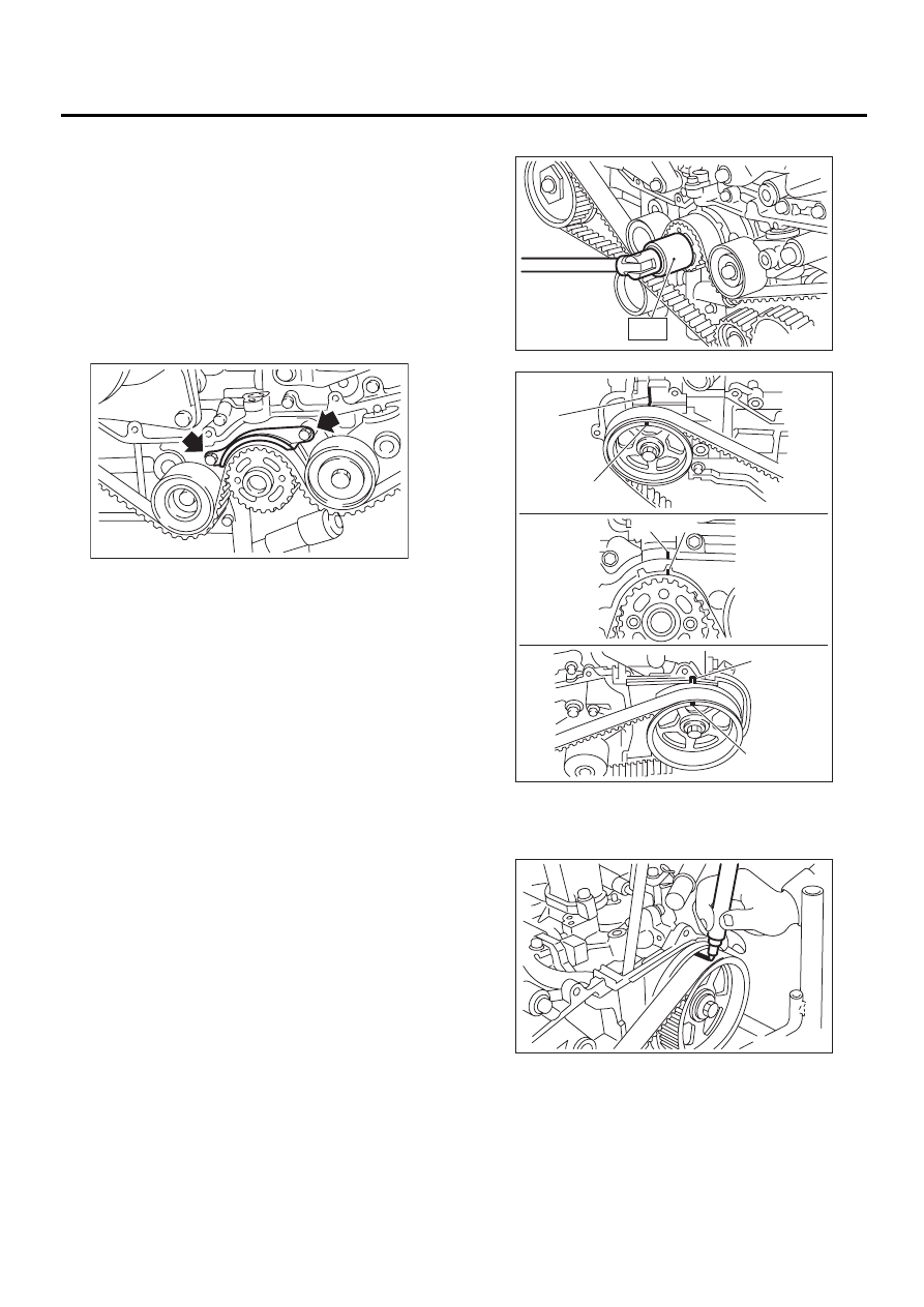
5) If the alignment mark (a) and/or arrow mark
(which indicates rotation direction) on timing belt
fade away, put new marks before removing the tim-
ing belt as shown in procedures below.
(1) Turn the crankshaft using ST. Align the
mark (a) of sprocket to cylinder block notch (b)
and ensure the right side cam sprocket mark (c),
cam cap and cylinder head matching surface (d)
and/or left side cam sprocket mark (e) and belt
cover notch (f) are properly adjusted.
ST
499987500
CRANKSHAFT SOCKET
(2) Using white paint, put alignment and/or ar-
row marks on the timing belts in relation to
crankshaft sprocket and cam sprockets.
ME-00230
ME-00231
ST
ME-00232
( a )
( b )
( c )
( d )
( e )
( f )
ME-00233
ME(H4SO)-47
MECHANICAL
TIMING BELT ASSEMBLY
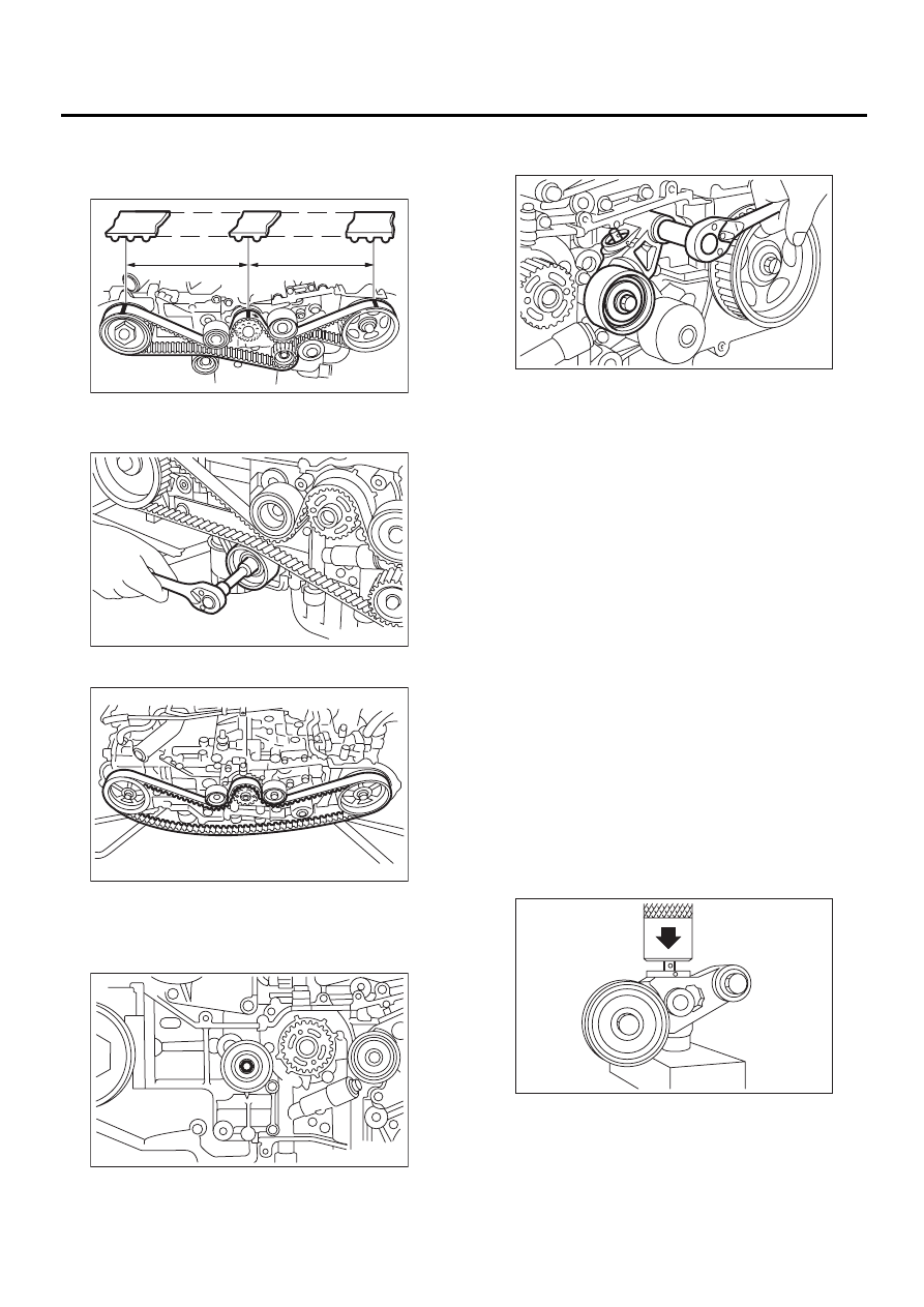
Specified data:
Z
1
: 46.8 tooth length
Z
2
: 43.7 tooth length
6) Remove the belt idler (No. 2).
7) Remove the belt idler No. 2.
8) Remove the timing belt.
2. BELT IDLER AND AUTOMATIC BELT
TENSION ADJUSTER ASSEMBLY
1) Remove the belt idler (No. 1).
2) Remove the automatic belt tension adjuster as-
sembly.
B: INSTALLATION
1. AUTOMATIC BELT TENSION ADJUST-
ER ASSEMBLY AND BELT IDLER
1) Preparation for installation of automatic belt ten-
sion adjuster assembly;
NOTE:
• Always use a vertical type pressing tool to move
the adjuster rod down.
• Do not use a lateral type vise.
• Push the adjuster rod vertically.
• Press-in the push adjuster rod gradually taking
more than 3 minutes.
• Do not allow press pressure to exceed 9,807 N
(1,000 kgf, 2,205 lb).
• Press the adjuster rod as far as the end surface
of the cylinder. Do not press the adjuster rod into
the cylinder. Doing so may damage the cylinder.
• Do not release the press pressure until stopper
pin is completely inserted.
(1) Attach the automatic belt tension adjuster
assembly to the vertical pressing tool.
(2) Slowly move the adjuster rod down with a
pressure of 294 N (30 kgf, 66 lb) until the adjust-
er rod is aligned with the stopper pin hole in the
cylinder.
ME-00234
Z
1
Z
2
ME-00235
ME-00236
ME-00237
ME-00238
ME-00239
Нет комментариевНе стесняйтесь поделиться с нами вашим ценным мнением.
Текст