Subaru Legacy III (2000-2003 year). Service manual — part 743
VDC-8
VDC (DIAGNOSTICS)
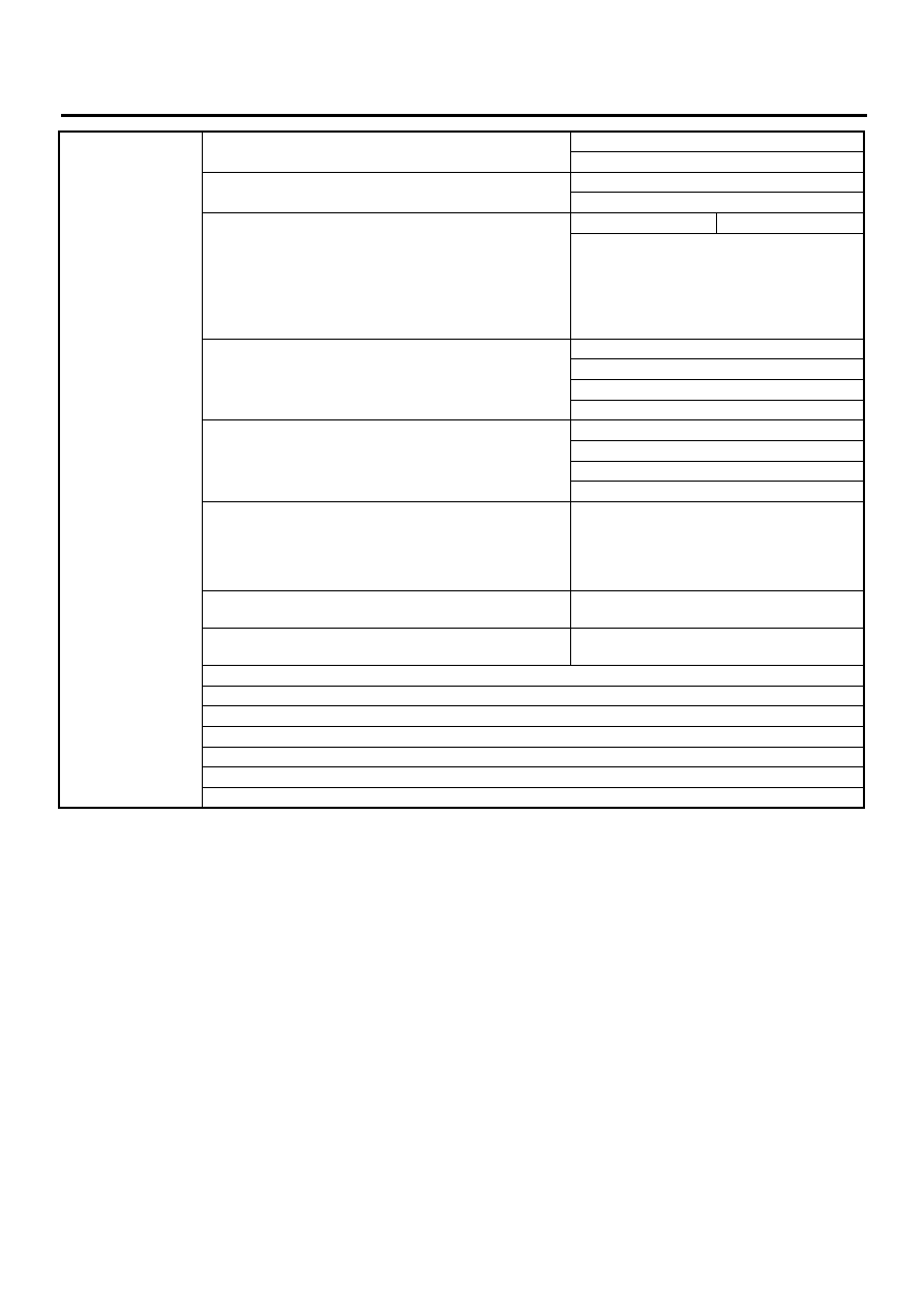
CHECK LIST FOR INTERVIEW
Condition
a) Brakes
Deceleration :
g
❏
Continuous /
❏
Intermittent
b) Accelerator
Acceleration :
g
❏
Continuous /
❏
Intermittent
c) Vehicle speed
km/h
MPH
❏
Advancing
❏
Accelerating
❏
Reducing speed
❏
Low speed
❏
Turning
❏
Others :
d) Tire inflation pressure
Front RH tire :
kPa
Front LH tire :
kPa
Rear RH tire :
kPa
Rear LH tire :
kPa
e) Degree of wear
Front RH tire :
Front LH tire :
Rear RH tire :
Rear LH tire :
f) Steering wheel
❏
Sharp turn
❏
Slow turn
❏
Straight-ahead operation
❏
Returned slowly
❏
Returned quickly
g) Tire/wheel size
❏
Specified
❏
Other than specified (
)
h) Tire type
❏
Summer tire
❏
Studless tire (Brand name:
)
i) Chain is passed around tires. :
❏
Yes /
❏
No
j) T tire is used. :
❏
Yes /
❏
No
k) Condition of suspension alignment :
l) Loading state :
m) Repair parts are used. :
❏
Yes /
❏
No
• What :
n) Others :
VDC-9
VDC (DIAGNOSTICS)
GENERAL DESCRIPTION
3. General Description
A: CAUTION
1. SUPPLEMENTAL RESTRAINT SYSTEM
“AIRBAG”
Airbag system wiring harness is routed near the
ABS sensor, ABS control module and hydraulic
control unit.
CAUTION:
• All airbag system wiring harness and con-
nectors are colored yellow. Do not use electri-
cal test equipment on these circuit.
• Be careful not to damage airbag system wir-
ing harness when servicing the ABS sensor,
ABS control module and hydraulic control unit.
B: INSPECTION
Before performing diagnostics, check the following
items which might affect VDC problems:
1. BATTERY
Measure battery voltage and specific gravity of
electrolyte.
Standard voltage: 12 V, or more
Specific gravity: Above 1.260
2. BRAKE FLUID
1) Check brake fluid level.
2) Check brake fluid leakage.
3. HYDRAULIC UNIT
Check the hydraulic unit VDC.
• With brake tester <Ref. to VDC-13, CHECKING
THE HYDRAULIC UNIT ABS OPERATION WITH
BRAKE TESTER, INSPECTION, Hydraulic Control
Unit (H/U).>
• Without brake tester <Ref. to VDC-14, CHECK-
ING THE HYDRAULIC UNIT VDC OPERATION
BY PRESSURE GAUGE, INSPECTION, Hydraulic
Control Unit (H/U).>
4. BRAKE DRAG
Check brake drag.
5. BRAKE PAD AND ROTOR
Check brake pad and rotor.
• Front <Ref. to BR-21, INSPECTION, Front
Brake Pad.><Ref. to BR-22, INSPECTION, Front
Disc Rotor.>
• Rear <Ref. to BR-26, INSPECTION, Rear Brake
Pad.><Ref. to BR-27, INSPECTION, Rear Disc
Rotor.>
6. TIRE
Check tire specifications, tire wear and air pres-
sure. <Ref. to WT-2, SPECIFICATIONS, General
Description.>
VDC-10
VDC (DIAGNOSTICS)
GENERAL DESCRIPTION
C: PREPARATION TOOL
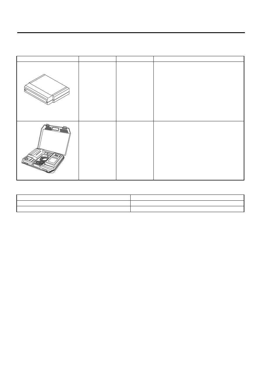
1. SPECIAL TOOLS
2. GENERAL PURPOSE TOOLS
ILLUSTRATION
TOOL NUMBER
DESCRIPTION
REMARKS
24082AA210
CARTRIDGE
Troubleshooting for electrical systems.
22771AA030
SELECT MONI-
TOR KIT
Troubleshooting for electrical systems.
• English: 22771AA030 (Without printer)
• German: 22771AA070 (Without printer)
• French: 22771AA080 (Without printer)
• Spanish: 22771AA090 (Without printer)
TOOL NAME
REMARKS
Circuit Tester
Used for measuring resistance, voltage and ampere.
Oscilloscope
Used for measuring sensor.
ST-2082AA210
ST22771AA030
VDC-11
VDC (DIAGNOSTICS)
ELECTRICAL COMPONENTS LOCATION
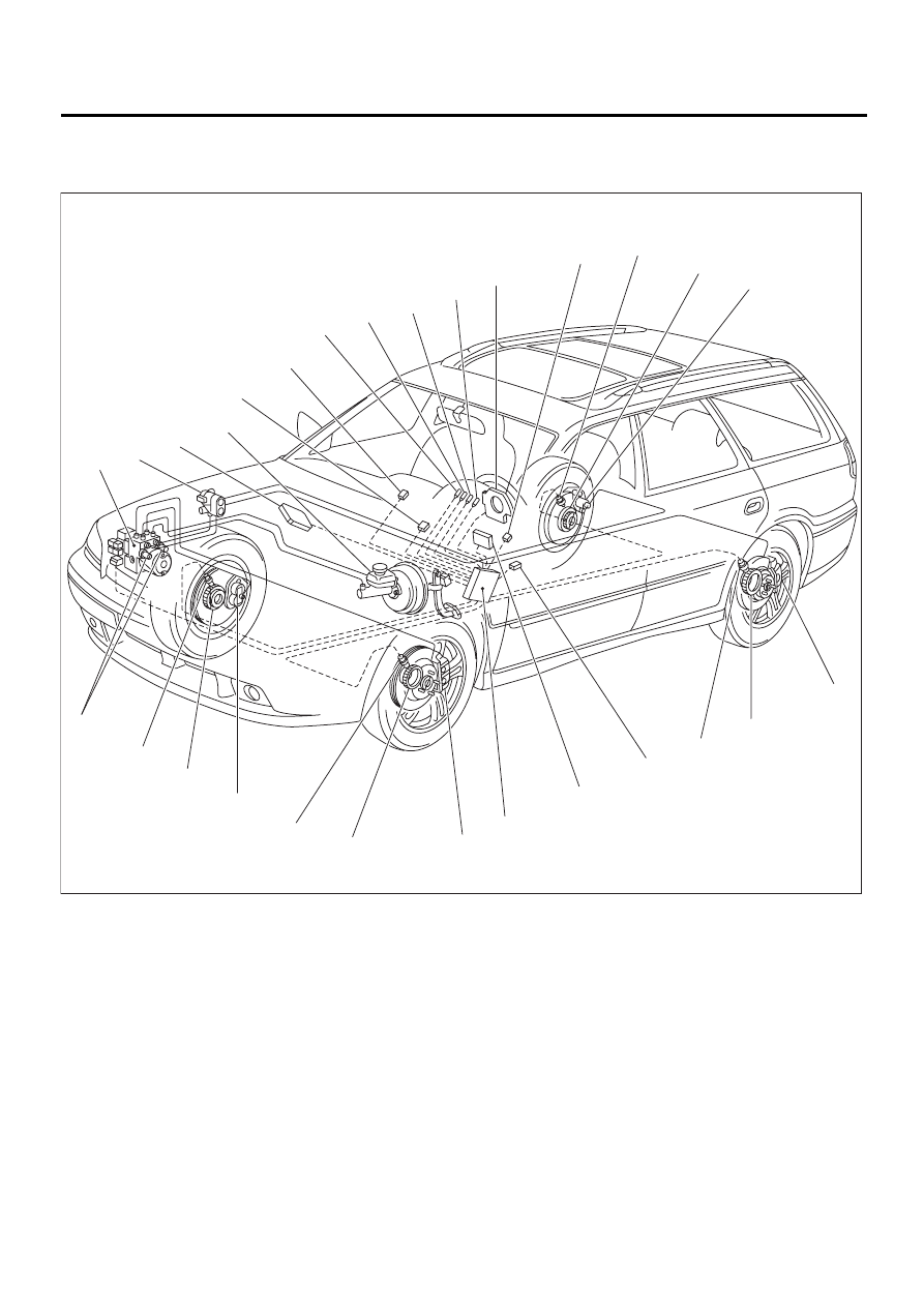
4. Electrical Components Location
A: LOCATION
(1) VDC hydraulic control unit (VDCH/
U)
(7) VDC warning light
(13) Tone wheel
(8) VDC operating indicator light
(14) Wheel cylinder
(2) Proportioning valve
(9) VDC OFF indicator light
(15) Yaw rate & lateral G sensor
(3) Engine control module
(10) Steering angle sensor
(16) Transmission control module
(4) Master cylinder
(11) Data link connector (for SUBARU
select monitor)
(17) VDC control module (VDCCM)
(5) Diagnosis connector
(18) Pressure sensor
(6) ABS warning light
(12) ABS sensor
(19) VDC OFF switch
VDC00116
( 1 )
( 2 )
( 3 )
( 4 )
( 5 )
( 6 )
( 7 )
( 8 )
( 9 )
(10)
(19)
(11)
(12)
(12)
(12)
(12)
(13)
(13)
(13)
(13)
(14)
(14)
(14)
(14)
(15)
(16)
(17)
(18)
Нет комментариевНе стесняйтесь поделиться с нами вашим ценным мнением.
Текст