Subaru Legacy III (2000-2003 year). Service manual — part 741
VDC-32
VDC
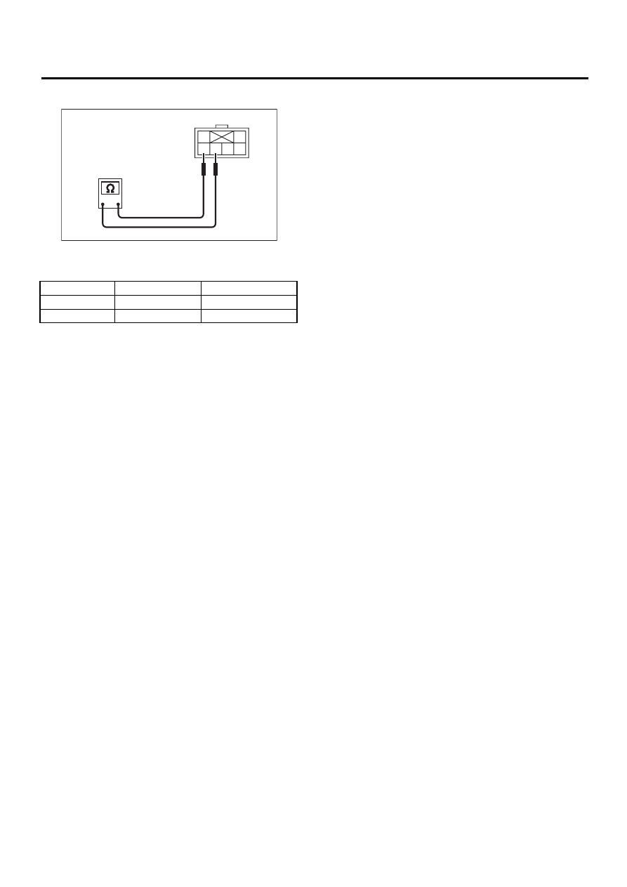
VDC OFF SWITCH
C: INSPECTION
Check continuity between VDC off switch termi-
nals.
If NG, replace VDC off switch.
Switch position
Tester connection
Specified condition
OFF
6 — 5
More than 1 M
Ω
ON
6 — 5
Less than 1
Ω
VDC00103
1
3
4
5
6
2
Off switch side

VDC (DIAGNOSTICS)
VDC
Page
Basic Diagnostic Procedure . . . . . . . . . . . . . . . . . . 2
Check List for Interview. . . . . . . . . . . . . . . . . . . ...6
General Description . . . . . . . . . . . . . . . . . . . . . 9
Electrical Components Location. . . . . . . . . . . . . . . . 11
Control Module I/O Signal . . . . . . . . . . . . . . . . . . .13
VDCCM Connector Cover . . . . . . . . . . . . . . . . . . .19
Subaru Select Monitor. . . . . . . . . . . . . . . . . . . ...20
Read Diagnostic Trouble Code (DTC) . . . . . . . . . . . . . ..23
Inspection Mode. . . . . . . . . . . . . . . . . . . . . . 24
Clear Memory Mode. . . . . . . . . . . . . . . . . . . . ..25
Warning Light Illumination Pattern . . . . . . . . . . . . . . . 26
List of Diagnostic Trouble Code (DTC) . . . . . . . . . . . . . .27
Diagnostics Chart with Diagnosis Connector . . . . . . . . . . . 33
Diagnostics Chart with Select Monitor . . . . . . . . . . . . . 130
General Diagnostic Table. . . . . . . . . . . . . . . . . . 275
VDC-2
VDC (DIAGNOSTICS)
BASIC DIAGNOSTIC PROCEDURE
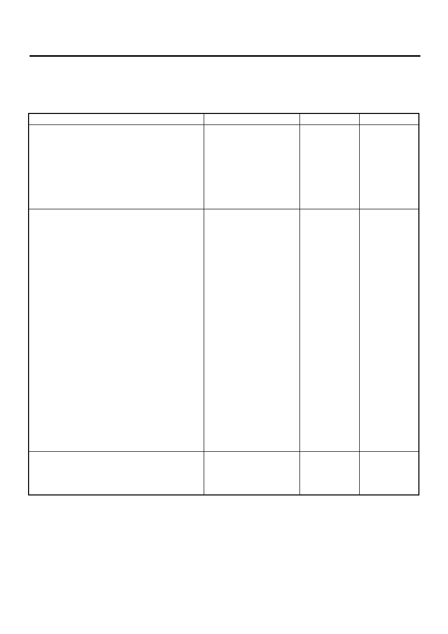
1. Basic Diagnostic Procedure
A: PROCEDURE
1. WITHOUT SUBARU SELECT MONITOR
Step
Value
Yes
No
1
CHECK PRE-INSPECTION.
1) Ask the customer when and how the trou-
ble occurred using interview checklist.
<Ref. to VDC-6, Check List for Interview.>
2) Before performing diagnosis, inspect unit
which might influence the VDC problem.
<Ref. to VDC-9, INSPECTION, General
Description.>
Is unit that might influence the VDC prob-
lem normal?
Normal
Repair or replace
each unit.
2
CHECK INDICATION OF DIAGNOSTIC
TROUBLE CODE (DTC).
Calling up diagnostic trouble code (DTC).
<Ref. to VDC-23, WITHOUT SUBARU
SELECT MONITOR, OPERATION, Read
Diagnostic Trouble Code (DTC).>
Is diagnostic trouble code (DTC) readable?
Can be read.
Inspect using diag-
nostic chart for
warning light fail-
ure. <Ref. to VDC-
33, ABS WARN-
ING LIGHT, VDC
WARNING LIGHT,
VDC OPERAT-
ING INDICATOR
LIGHT OR VDC
OFF INDICATOR
LIGHT DOES
NOT COME ON.,
Diagnostics Chart
with Diagnosis
Connector.>
NOTE:
Call up diagnostic
trouble code
(DTC) again after
inspecting warning
light. <Ref. to
VDC-23, WITH-
OUT SUBARU
SELECT MONI-
TOR, OPERA-
TION, Read
Diagnostic Trou-
ble Code (DTC).>
3
CHECK DIAGNOSTIC TROUBLE CODE
(DTC).
Is only the start code issued?
NOTE:
Record all diagnostic trouble codes (DTCs).
Only start code indicated.
VDC-3
VDC (DIAGNOSTICS)
BASIC DIAGNOSTIC PROCEDURE
CAUTION:
Remove foreign matter (dust, water, etc.) from the VDCCM connector during removal and installation.
NOTE:
• To check harness for broken wires or short circuits, shake it while holding it or the connector.
• When ABS and/or VDC warning light illuminates, read and record diagnostic trouble code (DTC) indicated
by ABS warning light.
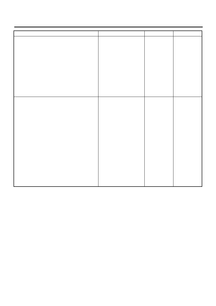
4
PERFORM THE GENERAL DIAGNOSTICS.
1) Inspect using “General Diagnostics Table”.
<Ref. to VDC-275, General Diagnostic
Table.>
2) Perform the clear memory mode. <Ref. to
VDC-25, WITHOUT SUBARU SELECT
MONITOR, OPERATION, Clear Memory
Mode.>
3) Perform the inspection mode. <Ref. to
VDC-24, Inspection Mode.>
Calling up the diagnostic trouble code
(DTC). <Ref. to VDC-23, WITHOUT SUB-
ARU SELECT MONITOR, OPERATION,
Read Diagnostic Trouble Code (DTC).>
Is only the start code issued?
Only start code indicated.
Complete the
diagnosis.
5
PERFORM THE DIAGNOSIS.
1) Inspect using “Diagnostics Chart with Diag-
nostic Connector”.<Ref. to VDC-33, Diag-
nostics Chart with Diagnosis Connector.>
NOTE:
For diagnostic trouble code (DTC) list, refer to
“List of Diagnostic Trouble Code (DTC)”. <Ref.
to VDC-27, WITHOUT SUBARU SELECT
MONITOR, LIST, List of Diagnostic Trouble
Code (DTC).>
2) Repair trouble cause.
3) Perform the clear memory mode. <Ref. to
VDC-25, WITHOUT SUBARU SELECT
MONITOR, OPERATION, Clear Memory
Mode.>
4) Perform the inspection mode. <Ref. to
5) Calling up the diagnostic trouble code
(DTC). <Ref. to VDC-23, WITHOUT SUB-
ARU SELECT MONITOR, OPERATION,
Read Diagnostic Trouble Code (DTC).>
Is only the start code issued?
Only start code indicated.
Complete the
diagnosis.
Inspect using
“Diagnostics Chart
with Diagnostic
Connector”. <Ref.
to VDC-33, Diag-
nostics Chart with
Diagnosis Con-
nector.>
Step
Value
Yes
No
Нет комментариевНе стесняйтесь поделиться с нами вашим ценным мнением.
Текст