Subaru Legacy III (2000-2003 year). Service manual — part 748
VDC-28
VDC (DIAGNOSTICS)
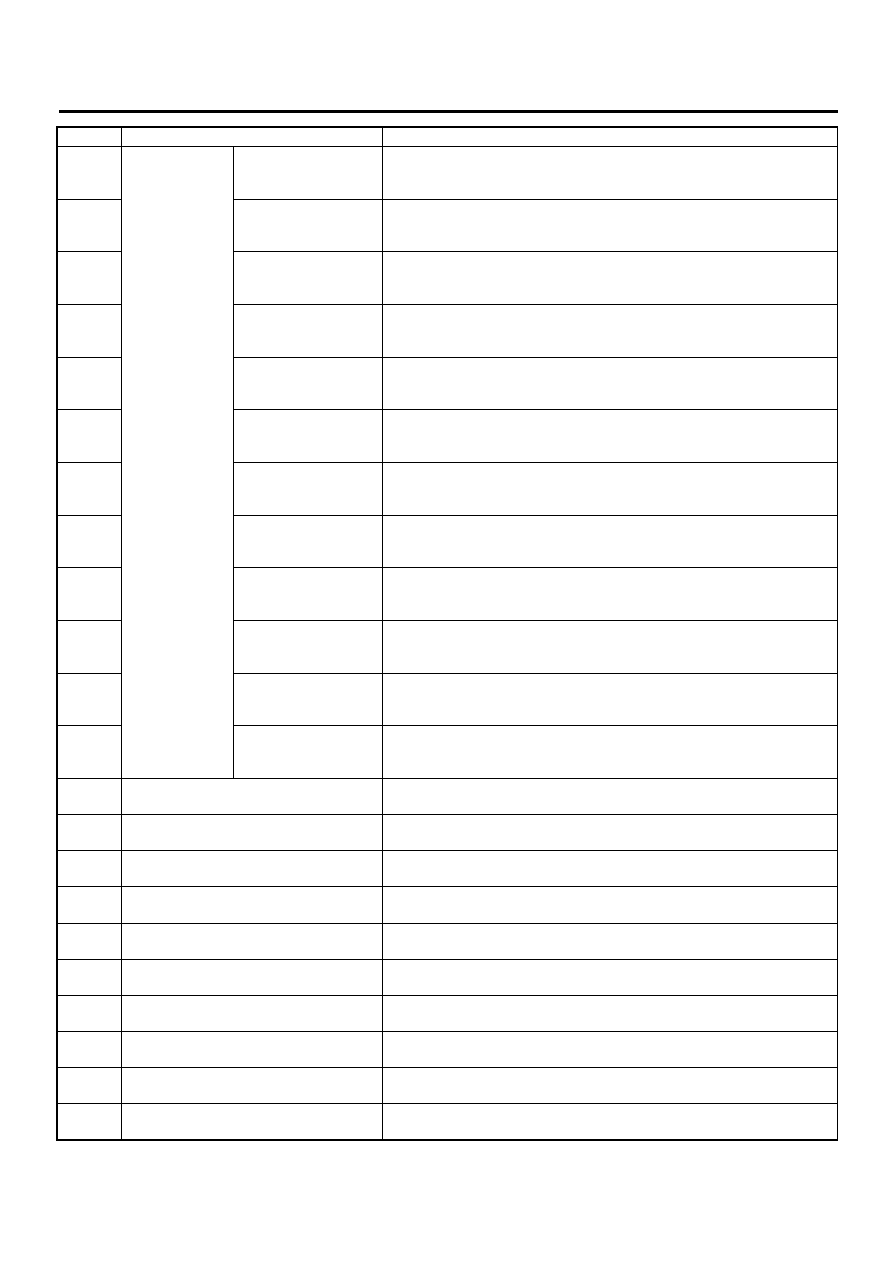
LIST OF DIAGNOSTIC TROUBLE CODE (DTC)
31
Abnormal sole-
noid valve cir-
cuit(s)
Front right inlet valve
32
Front right outlet valve
33
Front left inlet valve
34
Front left outlet valve
35
Rear right inlet valve
36
Rear right outlet valve
37
Rear left inlet valve
38
Rear left outlet valve
61
Primary cut valve
62
Secondary cut valve
63
Primary suction valve
64
Secondary suction
valve
41
Abnormal VDC control module
<Ref. to VDC-74, DTC 41 ABNORMAL VDC CONTROL MODULE, Diag-
nostics Chart with Diagnosis Connector.>
42
Source voltage is abnormal.
<Ref. to VDC-76, DTC 42 SOURCE VOLTAGE IS ABNORMAL., Diagnos-
tics Chart with Diagnosis Connector.>
43
Faulty VDCCM-ECM communication line
44
A communication with AT control abnor-
mal
45
Control module out of specification
46
Abnormal voltage of 5 V power supply
47
Faulty CAN communication line
48
Faulty ECM-VDCCM communication line
49
Abnormal engine speed signal
<Ref. to VDC-98, DTC 49 ABNORMAL ENGINE SPEED SIGNAL, Diag-
nostics Chart with Diagnosis Connector.>
51
Abnormal valve relay
<Ref. to VDC-100, DTC 51 ABNORMAL VALVE RELAY, Diagnostics
Chart with Diagnosis Connector.>
DTC No.
Contents of diagnosis
Index No.
VDC-29
VDC (DIAGNOSTICS)
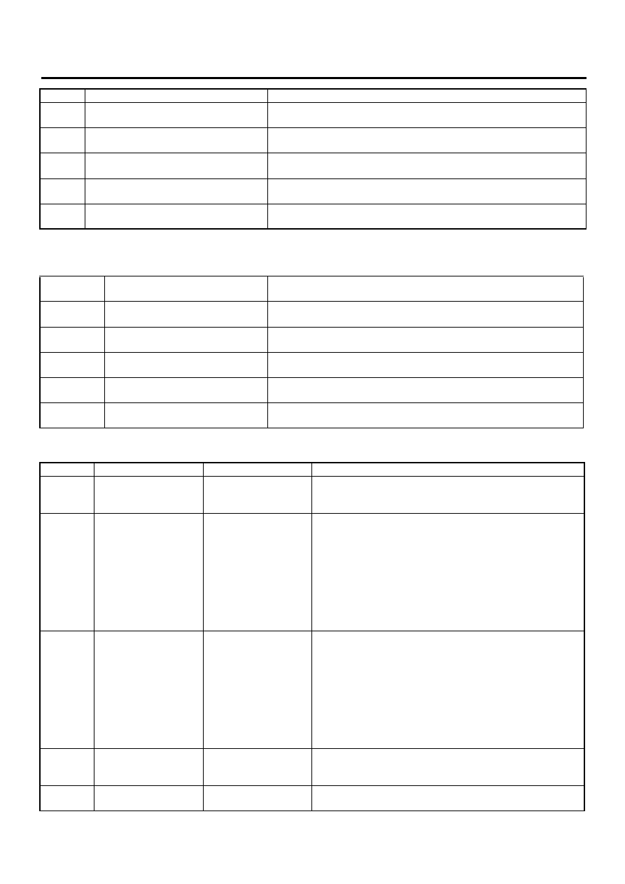
LIST OF DIAGNOSTIC TROUBLE CODE (DTC)
If any of the following multiple diagnostic trouble codes (DTCs) are present in memory, check the area cor-
responding to the first diagnostic trouble code (DTC). If no problem is detected, check the areas correspond-
ing to the other diagnostic trouble codes (DTCs) in order of their appearance.
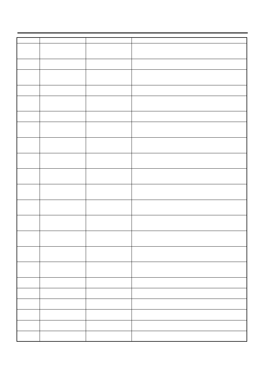
2. WITH SUBARU SELECT MONITOR
52
Abnormal motor and/or motor relay
71
Abnormal steering angle sensor
72
Abnormal yaw rate sensor
<Ref. to VDC-118, DTC 72 ABNORMAL YAW RATE SENSOR, Diagnos-
tics Chart with Diagnosis Connector.>
73
Abnormal lateral G sensor
<Ref. to VDC-122, DTC 73 ABNORMAL LATERAL G SENSOR, Diagnos-
tics Chart with Diagnosis Connector.>
74
Abnormal pressure sensor
<Ref. to VDC-126, DTC 74 ABNORMAL PRESSURE SENSOR, Diagnos-
tics Chart with Diagnosis Connector.>
Combination
of DTC No.
Problem area
Index No.
46, 74
(F87) — No. 78, 68 or 69 lead circuit
is shorted to ground or battery.
44, 71
(F87) — No. 83 or 81 lead circuit is
open.
51, 48, 71
(F87) — No. 27 lead circuit is open.
71, 51, 44
(F87) — No. 27 lead circuit is open.
72, 73
(F87) — No. 63 lead circuit is open.
<Ref. to VDC-122, DTC 73 ABNORMAL LATERAL G SENSOR, Diagnos-
tics Chart with Diagnosis Connector.>
DTC No.
Display screen
Contents of diagnosis
Index No.
—
Communication for ini-
tializing impossible
Select monitor commu-
nication failure
—
No trouble code
Although no diagnostic
trouble code appears
on the select monitor
display, the ABS warn-
ing light and/or VDC
warning light and/or
VDC operating indicator
light and/or VDC OFF
indicator light remains
on.
<Ref. to VDC-33, Diagnostics Chart with Diagnosis Connec-
tor.>
—
No trouble code
Although no diagnostic
trouble code appears
on the select monitor
display, the ABS warn-
ing light and/or VDC
warning light and/or
VDC operating indicator
light and/or VDC OFF
indicator light remains
off.
<Ref. to VDC-33, Diagnostics Chart with Diagnosis Connec-
tor.>
21
Front right ABS sensor
circuit open or shorted
battery
Open or short circuit in
front right ABS sensor
circuit
22
Front right ABS sensor
signal
Front right ABS sensor
abnormal signal
<Ref. to VDC-139, DTC 22 FRONT RIGHT ABS SENSOR SIG-
NAL, Diagnostics Chart with Select Monitor.>
DTC No.
Contents of diagnosis
Index No.
VDC-30
VDC (DIAGNOSTICS)
LIST OF DIAGNOSTIC TROUBLE CODE (DTC)
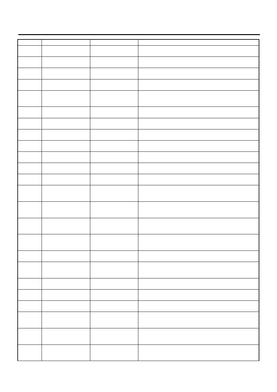
23
Front left ABS sensor
circuit open or shorted
battery
Open or short circuit in
front left ABS sensor
circuit
24
Front left ABS sensor
signal
Front left ABS sensor
abnormal signal
<Ref. to VDC-139, DTC 24 FRONT LEFT ABS SENSOR SIG-
NAL, Diagnostics Chart with Select Monitor.>
25
Rear right ABS sensor
circuit open or shorted
battery
Open or short circuit in
rear right ABS sensor
circuit
26
Rear right ABS sensor
signal
Rear right ABS sensor
abnormal signal
<Ref. to VDC-139, DTC 26 REAR RIGHT ABS SENSOR SIG-
NAL, Diagnostics Chart with Select Monitor.>
27
Rear left ABS sensor
circuit open or shorted
battery
Open or short circuit in
rear left ABS sensor cir-
cuit
28
Rear left ABS sensor
signal
Rear left ABS sensor
abnormal signal
<Ref. to VDC-140, DTC 28 REAR LEFT ABS SENSOR SIG-
NAL, Diagnostics Chart with Select Monitor.>
29
Any one of four ABS
sensor signal
Abnormal ABS sensor
signal on any one of
four sensor
<Ref. to VDC-146, DTC 29 ANY ONE OF FOUR ABS SENSOR
SIGNAL, Diagnostics Chart with Select Monitor.>
31
FR hold valve malfunc-
tion
Front right inlet sole-
noid valve
32
FR pressure reducing
valve malfunction
Front right outlet sole-
noid valve malfunction
33
FL hold valve malfunc-
tion
Front left inlet solenoid
valve malfunction
34
FL pressure reducing
valve malfunction
Front left outlet sole-
noid valve
35
RR hold valve malfunc-
tion
Rear right inlet solenoid
valve malfunction
36
RR pressure reducing
valve malfunction
Rear right outlet sole-
noid valve
37
RL hold valve malfunc-
tion
Rear left inlet solenoid
valve malfunction
38
RL pressure reducing
valve malfunction
Rear left outlet solenoid
valve
41
Electrical control mod-
ule
VDC control module
malfunction
42
Power supply voltage
low
Power supply voltage
too low
<Ref. to VDC-162, DTC 42 POWER SUPPLY VOLTAGE LOW,
Diagnostics Chart with Select Monitor.>
43
AET communication
line malfunction
AET communication
line malfunction
<Ref. to VDC-164, DTC 43 AET COMMUNICATION LINE
MALFUNCTION, Diagnostics Chart with Select Monitor.>
43
AEB communication
line malfunction
AEB communication
line malfunction
<Ref. to VDC-168, DTC 43 AEB COMMUNICATION LINE
MALFUNCTION, Diagnostics Chart with Select Monitor.>
43
AEC communication
line malfunction
AEC communication
line malfunction
<Ref. to VDC-172, DTC 43 AEC COMMUNICATION LINE
MALFUNCTION, Diagnostics Chart with Select Monitor.>
44
TCM communication
circuit
TCM communication
line malfunction
<Ref. to VDC-176, DTC 44 TCM COMMUNICATION CIRCUIT,
Diagnostics Chart with Select Monitor.>
45
Incorrect VDC control
module
Incorrect VDC control
module
<Ref. to VDC-178, DTC 45 INCORRECT VDC CONTROL
MODULE, Diagnostics Chart with Select Monitor.>
DTC No.
Display screen
Contents of diagnosis
Index No.
VDC-31
VDC (DIAGNOSTICS)
LIST OF DIAGNOSTIC TROUBLE CODE (DTC)
45
TCM malfunction speci-
fications
TCM malfunction speci-
fications
<Ref. to VDC-180, DTC 45 TCM MALFUNCTION SPECIFICA-
TIONS, Diagnostics Chart with Select Monitor.>
46
Abnormal voltage of 5 V
power supply
Abnormal voltage of 5 V
power supply
47
Improper CAN commu-
nication
CAN communication
line malfunction
<Ref. to VDC-186, DTC 47 IMPROPER CAN COMMUNICA-
TION, Diagnostics Chart with Select Monitor.>
48
Improper EAC commu-
nication
EAC communication
line malfunction
<Ref. to VDC-190, DTC 48 IMPROPER EAC COMMUNICA-
TION, Diagnostics Chart with Select Monitor.>
48
EAS communication
line grounding shorted
EAS communication
line grounding
48
Erroneous communica-
tion from EGI to VDC
Faulty ECM-VDCCM
communication line
49
Abnormal engine speed
signal
Abnormal engine speed
signal
<Ref. to VDC-200, DTC 49 ABNORMAL ENGINE SPEED SIG-
NAL, Diagnostics Chart with Select Monitor.>
51
Valve relay
Valve relay malfunction
<Ref. to VDC-202, DTC 51 VALVE RELAY, Diagnostics Chart
with Select Monitor.>
51
Valve relay ON failure
Valve relay ON failure
<Ref. to VDC-208, DTC 51 VALVE RELAY ON FAILURE, Diag-
nostics Chart with Select Monitor.>
52
Motor and motor relay
OFF failure
Motor and motor relay
OFF failure
<Ref. to VDC-214, DTC 52 MOTOR AND MOTOR RELAY OFF
FAILURE, Diagnostics Chart with Select Monitor.>
52
Motor and motor relay
ON failure
Motor and motor relay
ON failure
<Ref. to VDC-218, DTC 52 MOTOR AND MOTOR RELAY ON
FAILURE, Diagnostics Chart with Select Monitor.>
52
Motor malfunction
Motor malfunction
<Ref. to VDC-224, DTC 52 MOTOR MALFUNCTION, Diagnos-
tics Chart with Select Monitor.>
61
Normal opening valve 2
malfunction
Primary cut valve mal-
function
62
Normal opening valve 1
malfunction
Secondary cut valve
malfunction
63
Normal closing valve 2
malfunction
Primary suction valve
malfunction
64
Normal closing valve 1
malfunction
Secondary suction
valve malfunction
71
Steering angle sensor
offset is too big.
Steering angle sensor
offset is too big.
71
Change range of steer-
ing angle sensor is too
big.
Change range of steer-
ing angle sensor is too
big.
71
Steering angle sensor
malfunction
Steering angle sensor
malfunction
71
No signal from steering
angle sensor
No signal from steering
angle sensor
72
Abnormal yaw rate sen-
sor output
Abnormal yaw rate sen-
sor output
<Ref. to VDC-238, DTC 72 ABNORMAL YAW RATE SENSOR
OUTPUT, Diagnostics Chart with Select Monitor.>
72
Voltage inputted to yaw
rate sensor exceeds
specification.
Voltage inputted to yaw
rate sensor exceeds
specification.
72
Abnormal yaw rate sen-
sor reference voltage
Abnormal yaw rate sen-
sor reference voltage
72
Change range of yaw
rate sensor signal is too
big.
Change range of yaw
rate sensor signal is too
big.
DTC No.
Display screen
Contents of diagnosis
Index No.
Нет комментариевНе стесняйтесь поделиться с нами вашим ценным мнением.
Текст