Subaru Legacy III (2000-2003 year). Service manual — part 554
AT-110
AUTOMATIC TRANSMISSION
TORQUE CONVERTER CLUTCH CASE
B: INSTALLATION
1) Check the appearance of each component and
clean.
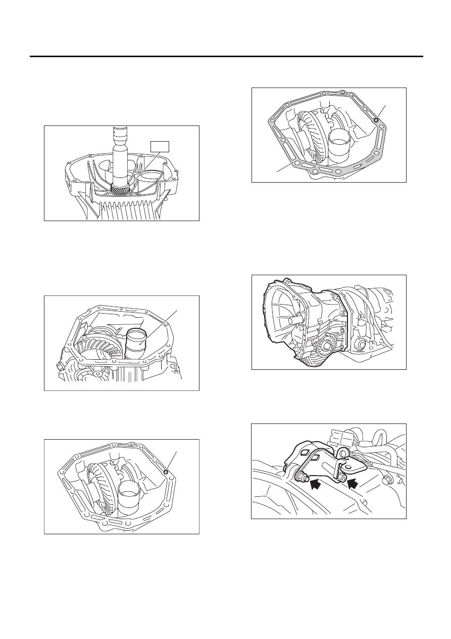
2) Force-fit the oil seal to the torque converter
clutch case with ST.
ST
398437700
DRIFT
3) Install the differential assembly to the case.
<Ref. to AT-124, INSTALLATION, Front Differen-
tial.>
4) Install the left and right side retainers. <Ref. to
AT-128, ADJUSTMENT, Front Differential.>
5) Install the new seal pipe to the torque converter
clutch case.
6) Install the rubber seal to the torque converter
clutch case.
7) Apply proper amount of liquid gasket to the en-
tire torque converter clutch case mating surface.
Liquid gasket:
THREE BOND 1215 (Part No. 004403007)
8) Install the torque converter clutch case assem-
bly without damaging bush and oil seal and secure
with six bolts and four nuts.
Tightening torque:
41 N·m (4.2 kgf-m, 30.4 ft-lb)
9) Install the pitching stopper bracket and transmis-
sion ground cable.
Tightening torque:
41 N·m (4.2 kgf-m, 30.4 ft-lb)
10) Insert inhibitor switch and transmission con-
nector into stay.
11) Install air breather hose. <Ref. to AT-83, IN-
STALLATION, Air Breather Hose.>
12) Install the oil cooler pipes. <Ref. to AT-80, IN-
STALLATION, ATF Cooler Pipe and Hose.>
(A) Seal pipe
(A) Rubber seal
AT-00177
ST
AT-00176
( A )
AT-00178
( A )
(A) THREE BOND 1215
(B) Rubber seal
AT-00179
( A )
( B )
AT-00175
AT-00173
AT-111
AUTOMATIC TRANSMISSION
TORQUE CONVERTER CLUTCH CASE
13) Install the oil charger pipe with O-ring. <Ref. to
AT-84, INSTALLATION, Oil Charger Pipe.>
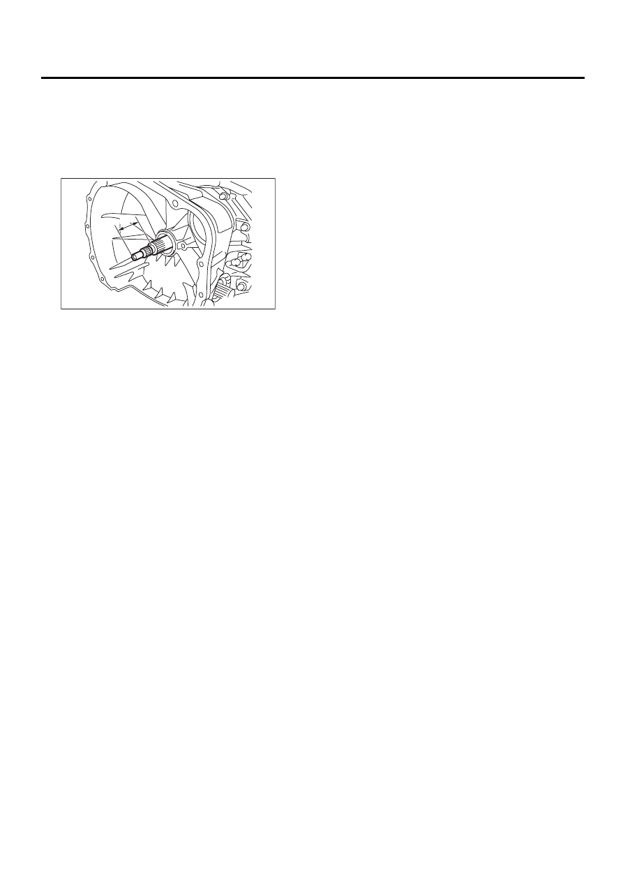
14) Insert the input shaft while turning lightly by
hand. At this time, not to damage the bushing.
Normal protrusion A:
50 — 55 mm (1.97 — 2.17 in)
15) Install the torque converter clutch assembly.
<Ref. to AT-85, INSTALLATION, Torque Converter
Clutch Assembly.>
16) Install the transmission assembly to the vehi-
cle. <Ref. to AT-42, INSTALLATION, Automatic
Transmission Assembly.>
C: INSPECTION
Measure the backlash and adjust to within specifi-
cations. <Ref. to AT-121, ADJUSTMENT, Drive
Pinion Shaft.>
AT-00291
A
AT-112
AUTOMATIC TRANSMISSION
OIL PUMP
34.Oil Pump
A: REMOVAL
1) Remove the transmission assembly from the ve-
hicle. <Ref. to AT-39, REMOVAL, Automatic
Transmission Assembly.>
2) Extract the torque converter clutch assembly.
<Ref. to AT-85, REMOVAL, Torque Converter
Clutch Assembly.>
3) Remove the input shaft.
4) Lift-up lever behind the transmission harness
connector and disconnect it from stay.
5) Disconnect inhibitor switch connector from stay.
6) Disconnect the air breather hose. <Ref. to AT-
83, REMOVAL, Air Breather Hose.>
7) Remove the oil charger pipe. <Ref. to AT-84,
REMOVAL, Oil Charger Pipe.>
8) Remove the oil cooler inlet and outlet pipes.
<Ref. to AT-78, REMOVAL, ATF Cooler Pipe and
Hose.>
9) Separation of torque converter clutch case and
transmission case sections <Ref. to AT-109, RE-
MOVAL, Torque Converter Clutch Case.>
10) Separate transmission case and extension
case sections. <Ref. to AT-86, REMOVAL, Exten-
sion Case.>
11) Remove the reduction drive gear. (MPT model)
<Ref. to AT-104, REMOVAL, Reduction Drive
Gear.>
12) Remove the center differential carrier. (VTD
model) <Ref. to AT-106, REMOVAL, Center Differ-
ential Carrier.>
13) Remove the reduction driven gear. <Ref. to AT-
101, REMOVAL, REMOVAL, Reduction Driven
Gear.>
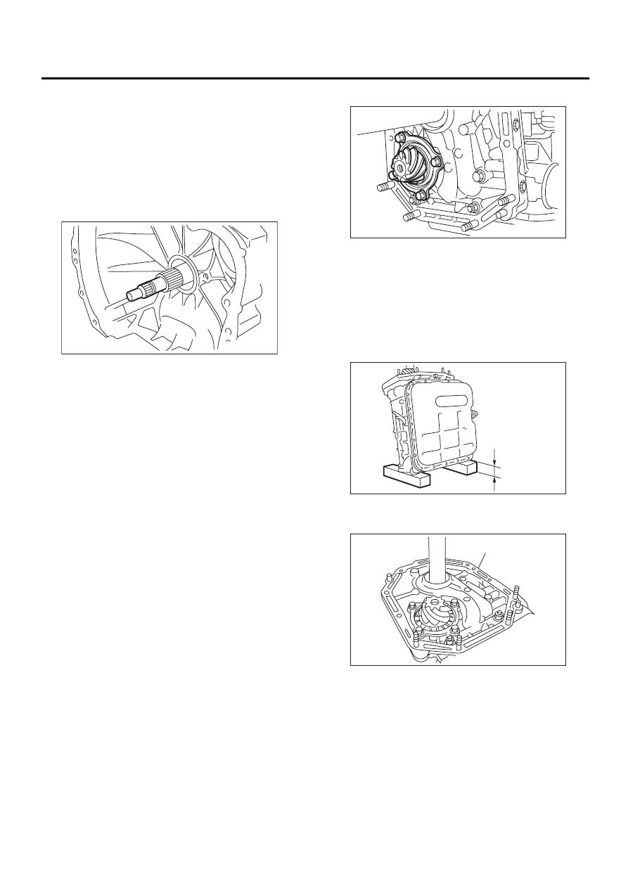
14) Loosen the taper roller bearing mounting bolts.
15) Place two wooden blocks on the workbench,
and stand the transmission case with its rear end
facing down.
NOTE:
• Be careful not to scratch the rear mating surface
of the transmission case.
• Note that the parking rod and drive pinion pro-
trude from the mating surface.
16) Remove the oil pump housing and adjusting
thrust washer.
AT-00114
(A) Oil pump housing
AT-00180
AT-00181
(2.17 in)
55 mm
AT-00182
( A )
AT-113
AUTOMATIC TRANSMISSION
OIL PUMP
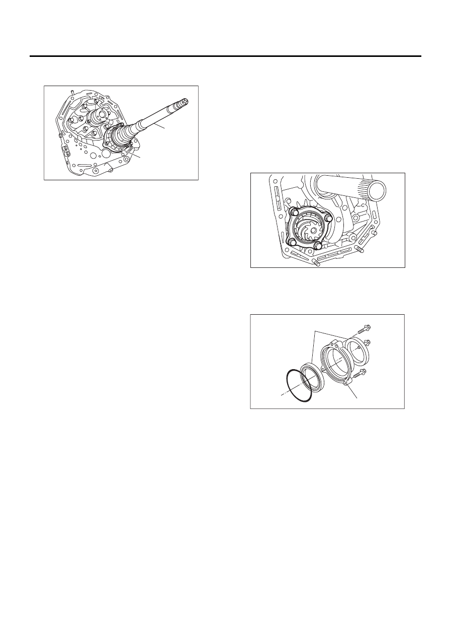
17) Remove the oil seal retainer.
Also remove the O-ring and oil seal (air breather).
18) Remove O-rings from oil pump housing.
19) Remove the drive pinion assembly.
B: INSTALLATION
1) Assemble the drive pinion assembly to the oil
pump housing.
NOTE:
• Be careful not to bend the shims.
• Be careful not to force the pinion against the
housing bore.
2) Tighten four bolts to secure the roller bearing.
Tightening torque:
40 N·m (4.1 kgf-m, 30 ft-lb)
3) With pay attention to the orientation of the oil
seals, install two new oil seals to the oil seal retain-
er using ST.
ST
499247300
INSTALLER
(A) Oil seal retainer
(B) Drive pinion shaft
AT-00183
( A )
( B )
(A) Oil seal
(B) Oil seal retainer
AT-00184
AT-00185
( A )
( B )
Нет комментариевНе стесняйтесь поделиться с нами вашим ценным мнением.
Текст