Subaru Legacy III (2000-2003 year). Service manual — part 448
LU(H4DOSTC)-12
LUBRICATION
OIL PUMP
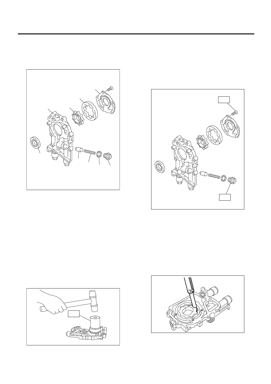
C: DISASSEMBLY
Remove screws which secure oil pump cover and
disassemble oil pump. Inscribe alignment marks on
inner and outer rotors so that they can be replaced
in their original positions during reassembly.
D: ASSEMBLY
1) Install front oil seal by using ST.
ST
499587100
OIL SEAL INSTALLER
NOTE:
Use a new oil seal.
2) Apply engine oil to inner and outer rotors.
3) Install inner and outer rotors in their original po-
sitions.
4) Install oil relief valve and relief valve spring.
5) Install oil pump cover.
Tightening torque:
T1: 5 N·m (0.5 kgf-m, 3.6 ft-lb)
T2: 44 N·m (4.5 kgf-m, 33 ft-lb)
E: INSPECTION
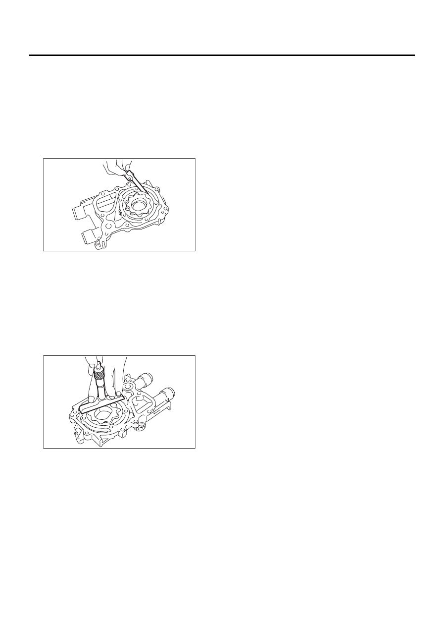
1. TIP CLEARANCE
Measure the tip clearance of rotors. If the clearance
exceeds the limit, replace rotors as a set.
Tip clearance:
Standard
0.04 — 0.14 mm (0.0016 — 0.0055 in)
Limit
0.18 mm (0.0071 in)
(A) Oil seal
(B) Pump case
(C) Inner rotor
(D) Outer rotor
(E) Pump cover
(F) Relief valve
(G) Relief valve spring
(H) Plug
(I) Gasket
LU-00020
( A )
( B )
( C )
( D )
( E )
( F )
( G )
( H )
( I )
LU-00021
ST
T1
T2
LU-00022
LU-00023
LU(H4DOSTC)-13
LUBRICATION
OIL PUMP
2. CASE CLEARANCE
Measure the clearance between the outer rotor and
the oil pump rotor housing. If the clearance ex-
ceeds the limit, replace the rotor.
Case clearance:
Standard
0.10 — 0.175 mm (0.0039 — 0.0069 in)
Limit
0.20 mm (0.0079 in)
3. SIDE CLEARANCE
Measure clearance between oil pump inner rotor
and pump cover. If the clearance exceeds the limit,
replace rotor or pump body.
Side clearance:
Standard
0.02 — 0.07 mm (0.0008 — 0.0028 in)
Limit
0.12 mm (0.0047 in)
4. OIL RELIEF VALVE
Check the valve for fitting condition and damage,
and the relief valve spring for damage and deterio-
ration. Replace the parts if defective.
Relief valve spring:
Free length
73.7 mm (2.902 in)
Installed length
54.7 mm (2.154 in)
Load when installed
93.1 N (9.49 kgf, 20.93 lb)
5. OIL PUMP CASE
Check the oil pump case for worn shaft hole,
clogged oil passage, worn rotor chamber, cracks,
and other faults.
6. OIL SEAL
Check the oil seal lips for deformation, hardening,
wear, etc. and replace if defective.
LU-00024
LU-00025
LU(H4DOSTC)-14
LUBRICATION
OIL PAN AND STRAINER
5. Oil Pan and Strainer
A: REMOVAL
1) Set the vehicle on lift arms.
2) Remove front wheels.
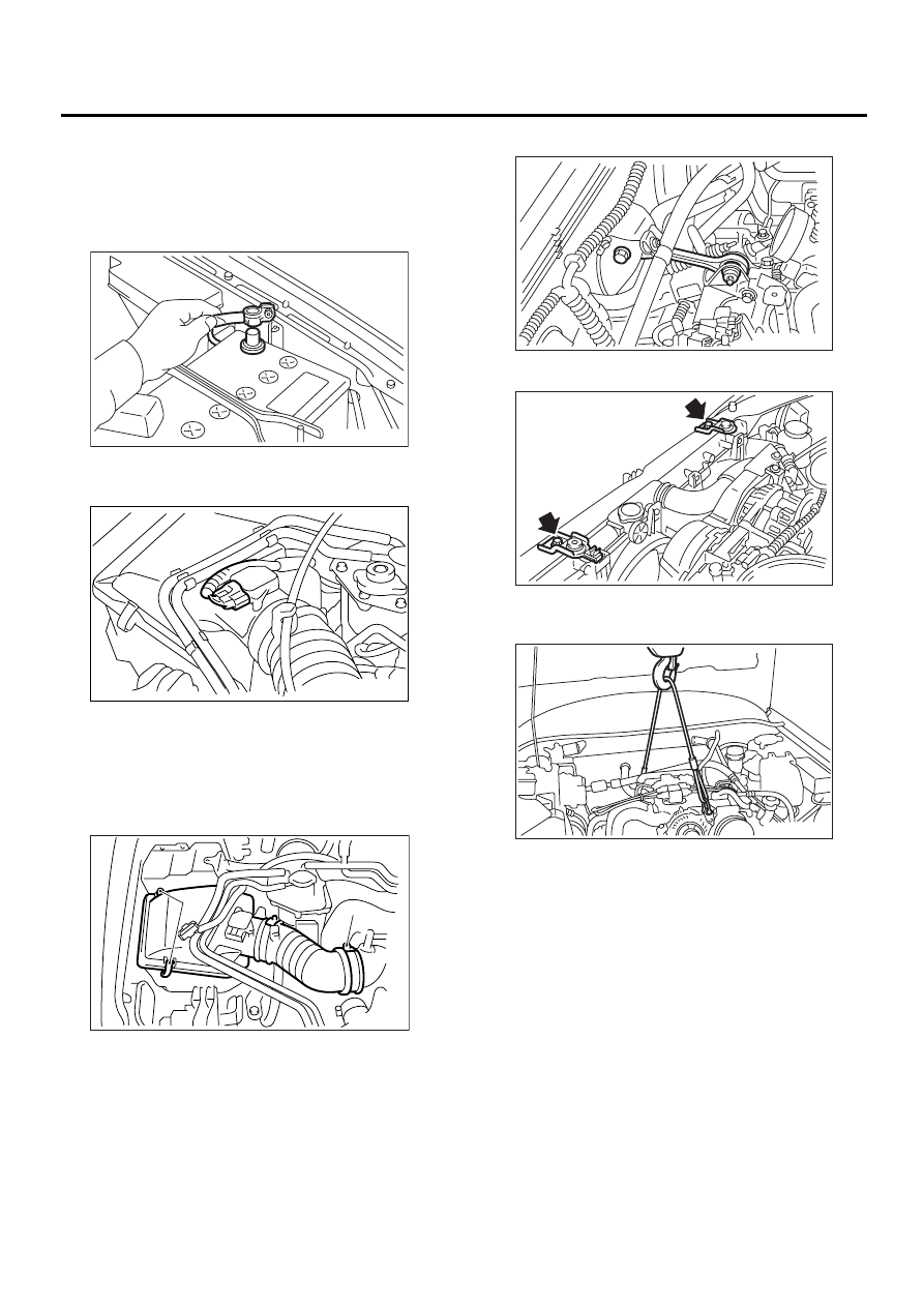
3) Disconnect battery ground cable.
4) Disconnect the connector from mass air flow
sensor.
5) Loosen the clamp (A) which connects air intake
boot to intake duct.
6) Remove the two clips (B) from air cleaner upper
cover.
7) Remove the air intake boot and air cleaner upper
cover.
8) Remove the intercooler. <Ref. to IN(H4DOSTC)-
13, REMOVAL, Intercooler.>
9) Remove pitching stopper.
10) Remove radiator upper brackets.
11) Support engine with a lifting device and wire
ropes.
12) Lift-up the vehicle.
CAUTION:
When lifting up the vehicle, wire rope must be
raised at the same time.
13) Remove under cover.
FU-00009
LU-00026
(B)
(A)
LU-00153
ME-00213
LU-00097
LU-00028
LU(H4DOSTC)-15
LUBRICATION
OIL PAN AND STRAINER
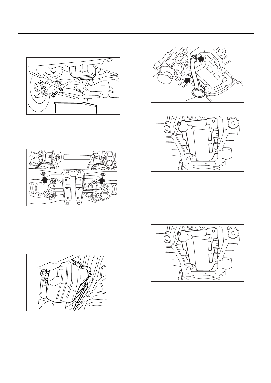
14) Drain engine oil.
Set container under the vehicle, and remove drain
plug from oil pan.
15) Remove nuts which secure front cushion rub-
ber onto front crossmember.
16) Remove bolts which secure oil pan on cylinder
block while raising up engine.
17) Insert oil pan cutter blade between cylinder
block-to-oil pan clearance.
CAUTION:
Do not use a screwdriver or similar tool in place
of oil pan cutter.
18) Remove oil strainer.
19) Remove baffle plate.
B: INSTALLATION
NOTE:
Before installing oil pan, clean sealant from oil pan
and engine block.
1) Install baffle plate.
Tightening torque:
6.4 N·m (0.65 kgf-m, 4.7 ft-lb)
(A) Gasket
(B) Drain plug
LU-00151
(B)
(A)
LU-00030
LU-00031
LU-00032
LU-00033
LU-00033
Нет комментариевНе стесняйтесь поделиться с нами вашим ценным мнением.
Текст