Subaru Legacy III (2000-2003 year). Service manual — part 446
LU(H4DOSTC)-4
LUBRICATION
GENERAL DESCRIPTION
C: CAUTION
• Wear working clothing, including a cap, protec-
tive goggles, and protective shoes during opera-
tion.
• Remove dirt and corrosion before removal, in-
stallation or disassembly.
• Keep the disassembled parts in order and pro-
tect them from dust or dirt.
• Before removal, installation or disassembly, be
sure to clarify the failure. Avoid unnecessary re-
moval, installation, disassembly, and replacement.
• Be careful not to burn your hands, because each
part in the vehicle is hot after running.
• Be sure to tighten fasteners including bolts and
nuts to the specified torque.
• Place shop jacks or safety stands at the specified
points.
• Before disconnecting electrical connectors of
sensors or units, be sure to disconnect ground ca-
ble from battery.
LU(H4DOSTC)-5
LUBRICATION
GENERAL DESCRIPTION
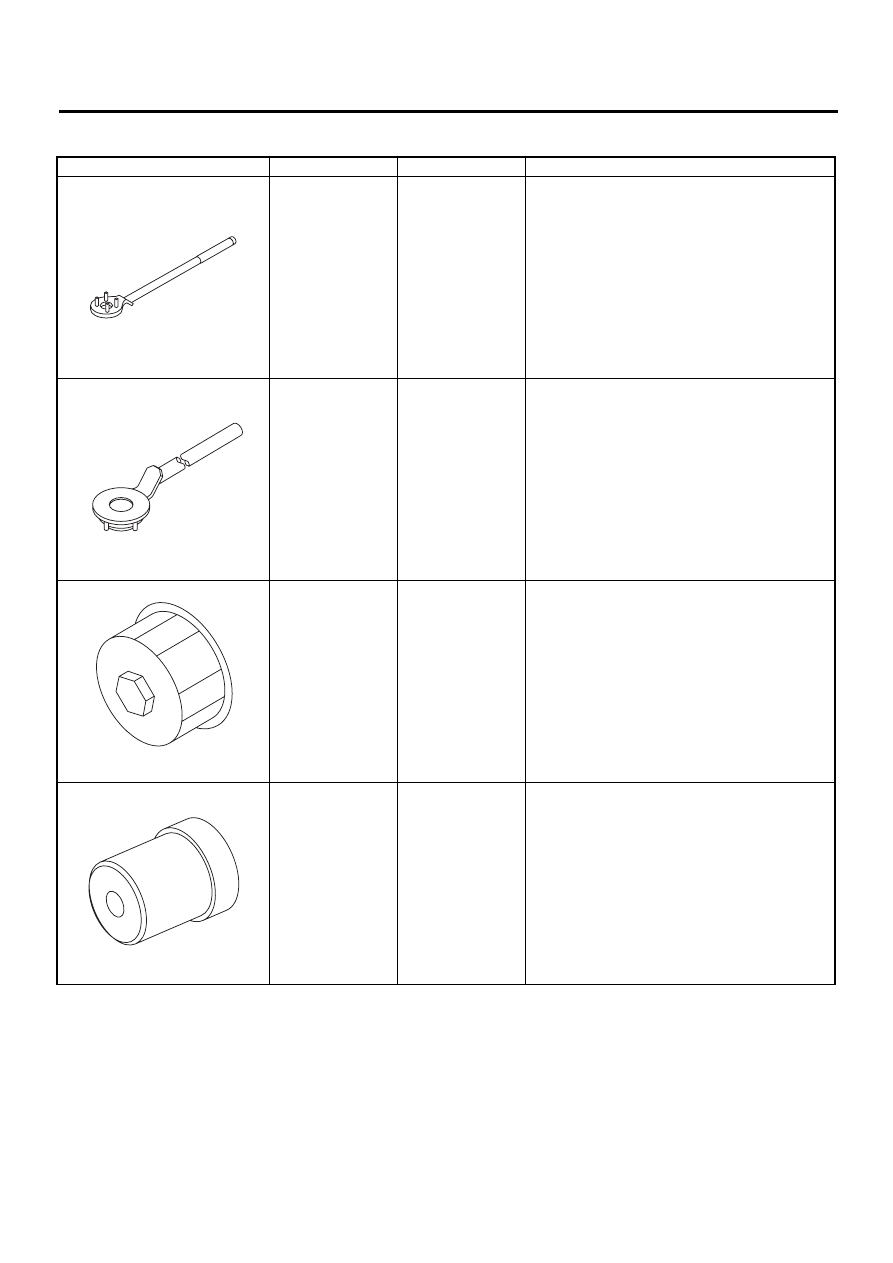
D: PREPARATION TOOL
ILLUSTRATION
TOOL NUMBER
DESCRIPTION
REMARKS
499977100
(MT model)
CRANKSHAFT
PULLEY
WRENCH
Used for stopping rotation of crankshaft pulley
when loosening and tightening crankshaft pulley
bolt.
499977400
(AT model)
CRANKSHAFT
PULLEY
WRENCH
Used for stopping rotation of crankshaft pulley
when loosening and tightening crankshaft pulley
bolt.
498547000
OIL FILTER
WRENCH
Used for removing and installing oil filter.
499587100
OIL SEAL
INSTALLER
Used for installing oil pump oil seal.
ST-499977100
ST-499977400
ST-498547000
ST-499587100
LU(H4DOSTC)-6
LUBRICATION
OIL PRESSURE SYSTEM
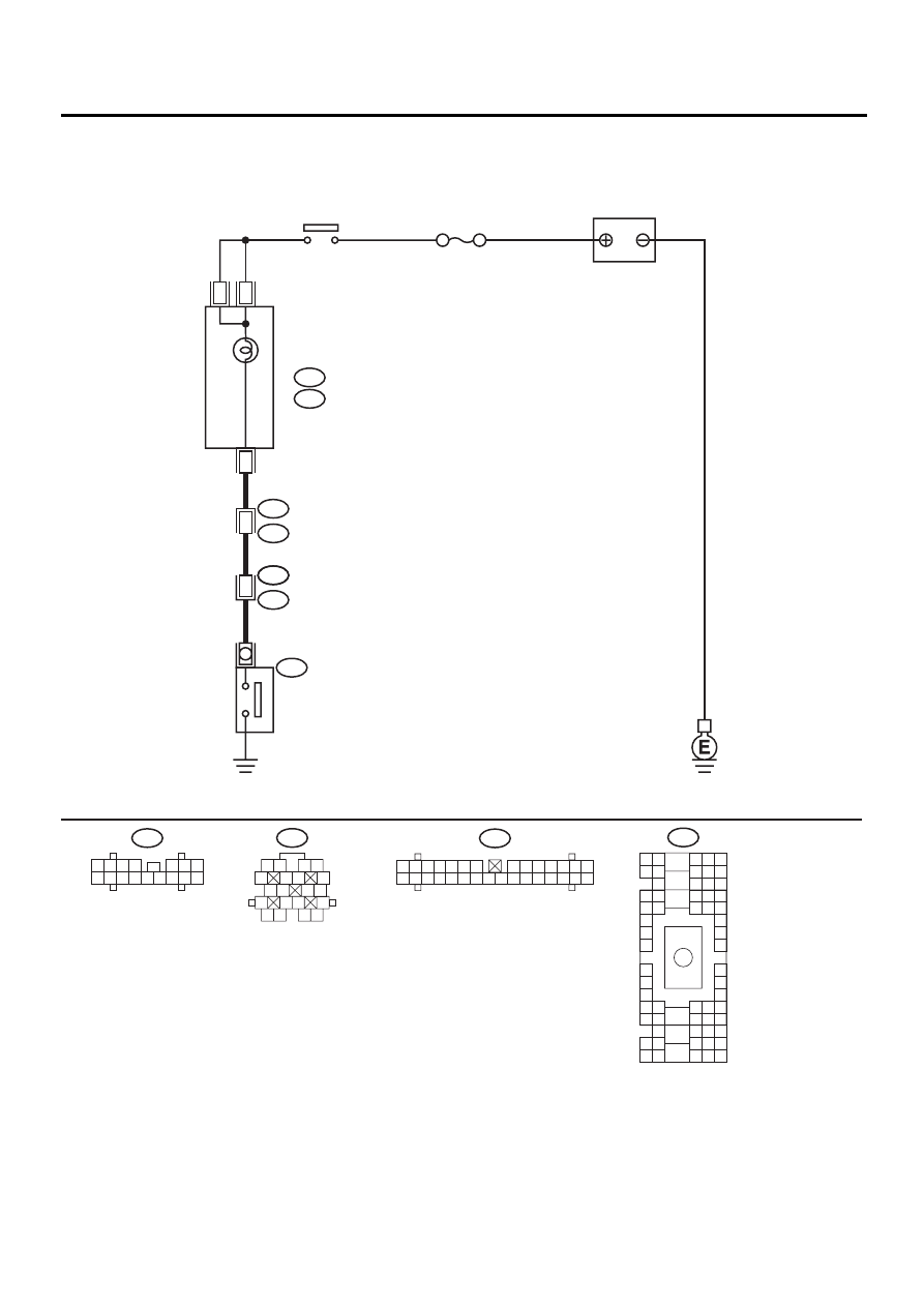
2. Oil Pressure System
A: SCHEMATIC
LU-00150
B21
1 2
3 4
5
6 7
8
9 10
11 12
13
14 15
16
17 18
19 20
B36
B4 B5 B6
A4 A5 A6
C5 C6
F6
D4 D5 D6
F1
H1
C4
G6
G1
C2
K1
M1 M2
K6
L1
D1 D2
A1 A2
B1 B2
I6
J6
L2
I1
J1
H6
M4 M5 M6
L4 L5 L6
N5 N6
O4 O5 O6
N4
P4 P5
N2
O1 O2
P1 P2
N3
O3
P3
P6
A3
B3
C3
E4 E5 E6
E1 E2
OIL PRESSURE
W
ARNING LIGHT
B5
B8
B5
14
i1
B36
E2
E11
B21
OIL PRESSURE
SWITCH
NO.5
IGNITION
RELAY
SMJ
COMBINATION
METER
i10
A:
i11
B:
BATTERY
A8
i11
1 2 3
8 9 10
4
11 12 13 14 15 16
5 6 7
i10
1 2 3 4 5 6 7
8 9 10 11 12 13 14
15 16 17 18 19 20 21 22 23 24 25 26 27 28 29 30

LU(H4DOSTC)-7
LUBRICATION
OIL PRESSURE SYSTEM
B: INSPECTION
Step
Value
Yes
No
1
CHECK COMBINATION METER.
1) Turn ignition switch to ON. (engine OFF)
2) Check other warning lights.
Does the warning lights go on?
Warning light goes on.
Repair or replace
the combination
meter. <Ref. to
IDI-4, INSPEC-
TION, Combina-
tion Meter
System.>
2
CHECK HARNESS CONNECTOR BETWEEN
COMBINATION METER AND OIL PRES-
SURE SWITCH.
1) Turn ignition switch to OFF.
2) Disconnect connector from the oil pressure
switch.
3) Turn ignition switch ON.
4) Measure the voltage of harness between
the combination meter connector and chas-
sis ground.
Connector & terminal
(E11) No. 1 — Chassis ground:
Does the measured value exceed the spec-
ified value?
10 V
Replace oil pres-
sure switch.
3
CHECK COMBINATION METER.
1) Turn ignition switch to OFF.
2) Remove the combination meter.
3) Measure the resistance of the combination
meter.
Terminal
No. A8 — No. B8:
No. B5 — No. B8:
Is the measured value less than the speci-
fied value?
10
Ω
Replace the har-
ness connector
between combina-
tion meter and oil
pressure switch.
Repair or replace
the combination
meter and the oil
pressure switch
warning light bulb.
Нет комментариевНе стесняйтесь поделиться с нами вашим ценным мнением.
Текст